XXA18B1PM12
Ultrasonic sensors XX, ultrasonic sensor cylindrical 90 deg M18, Sn=1 m, PNP, SYNC, connector M12

COMMERCIALISED
Expand all
Datasheet
Range of product
Telemecanique Ultrasonic sensors XX
Sensor type
Ultrasonic sensor
Series name
General purpose
Sensor name
XXA
Sensor design
Cylindrical M18
Detection system
Diffuse (with 90° head)
Material
Metal
Type of output signal
Discrete
Discrete output function
1 NO or 1 NC programmable
Wiring technique
5-wire
[Us] rated supply voltage
12...24 V DC with reverse polarity protection
Discrete output type
PNP
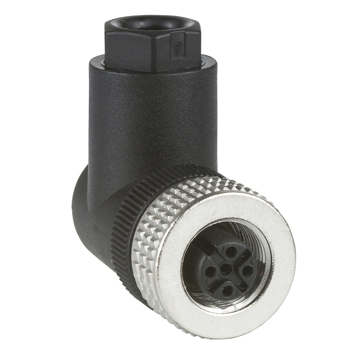
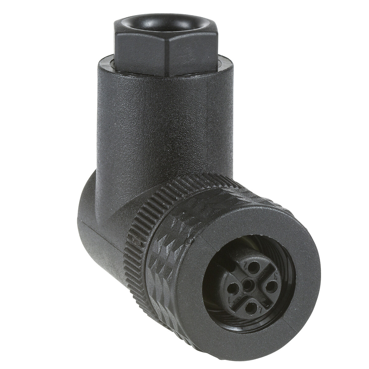
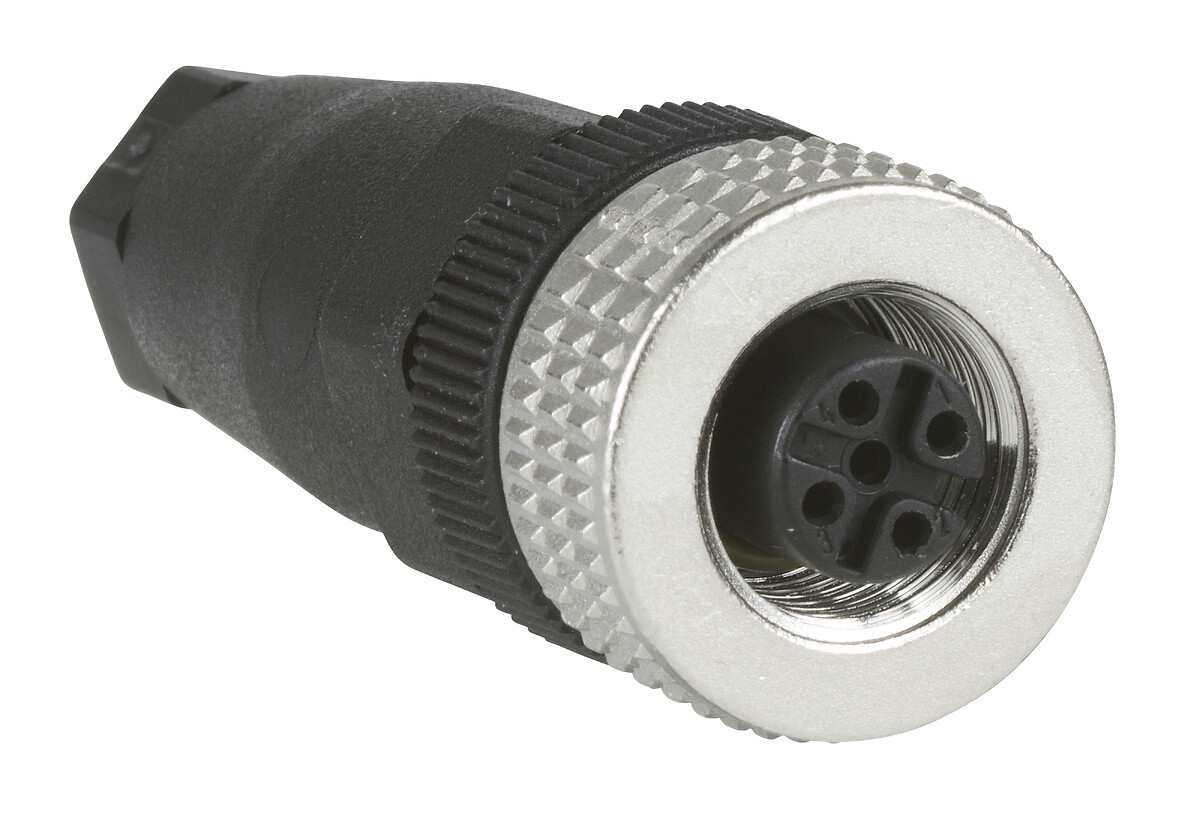
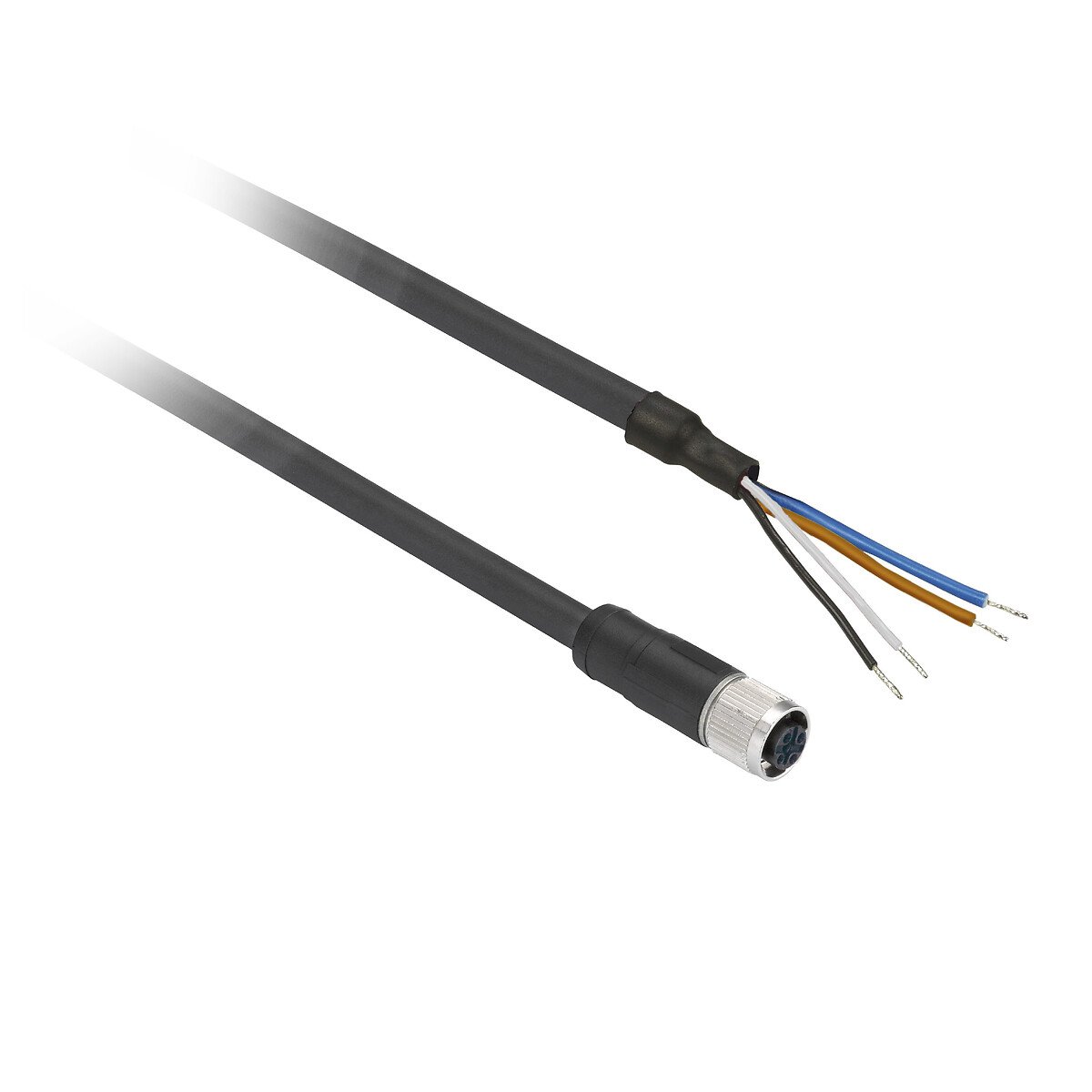
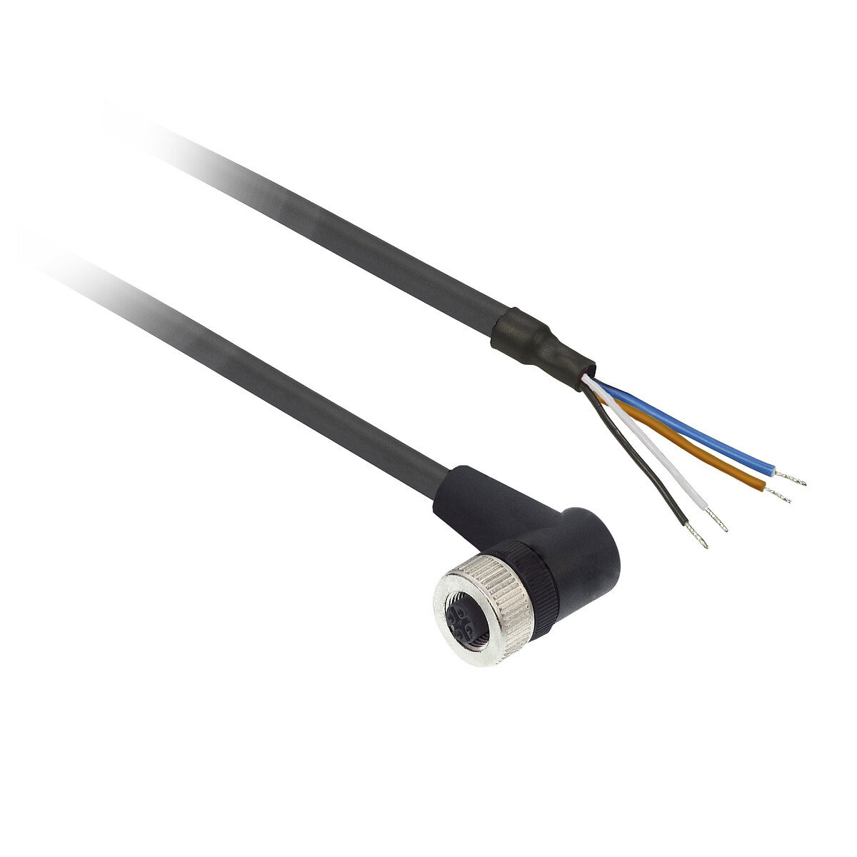
Electrical connection
Male connector M12 5 pins
Enclosure material
Nickel plated brass
Front material
Epoxy
resin
rubber
resin
rubber
Function available
Software configurable
with synchronisation mode
with synchronisation mode
Voltage drop
2 VOLT
Minimum size of detected object
Cylinder diameter 1 mm at 600 mm
Delay first up
120 MILLISECOND
Current consumption
30 mA
Status LED
Output state: 1 LED (yellow), echo state: 1 LED (green)
Setting-up
Configurator software
teach mode
teach mode
Switching frequency
11 Hz
Delay response
45 MILLISECOND
Delay recovery
45 MILLISECOND
IP degree of protection
IP65 conforming to IEC 60529, IP67
Marking
CE
Standards
CSA C22.2 No 14
IEC 60947-5-2
UL 508
IEC 60947-5-2
UL 508
Product certifications
cULus
E2
Ecolab
RCM
E2
Ecolab
RCM
Vibration resistance
+/-1 mm conforming to IEC 60068-2-6 (f = 10-55 Hz)
Shock resistance
30 gn in all 3 axes for 11 ms conforming to IEC 60068-2-27
Unit type of package 1
PCE
Number of units in package 1
1
Package 1 height
8.89 CENTIMETER
Package 1 width
8.64 CENTIMETER
Package 1 length
4.06 CENTIMETER
Package 1 weight
0.08 KILOGRAM
Unit type of package 3
CAR
Number of units in package 3
1
Package 3 height
4.1 CENTIMETER
Package 3 width
6.4 CENTIMETER
Package 3 length
9.4 CENTIMETER
Unit type of package 2
S01
Package 3 weight
0.05 KILOGRAM
Number of units in package 2
15
Package 2 height
15 CENTIMETER
Package 2 width
15 CENTIMETER
Package 2 length
40 CENTIMETER
Package 2 weight
0.975 KILOGRAM
Indivisible sale quantity
1
California proposition 65
WARNING: This product can expose you to chemicals including: Diisononyl phthalate (DINP), which is known to the State of California to cause cancer, and Di-isodecyl phthalate (DIDP), which is known to the State of California to cause birth defects or other reproductive harm. For more information go to www.P65Warnings.ca.gov
Expand all
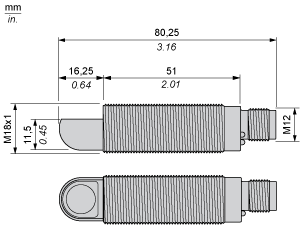
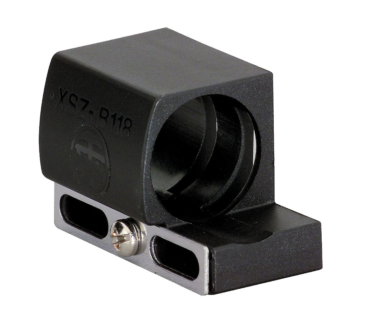
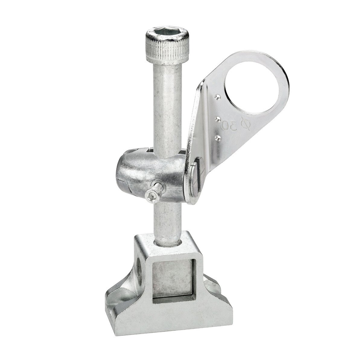
Technical Drawings
Dimensions
Connections
Connector Wiring
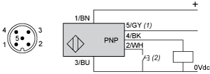
- (1) : Synchronization
- (2) : External setting pushbutton or XXZPB100 remote teach pushbutton.
Connections
Wiring Scheme
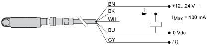
- (1) : Synchronization
- (2) : External setting pushbutton or XXZPB100 remote teach pushbutton.
- (1) : Synchronization
Connections
Wiring for the Synchronization Function (Side by Side Application)
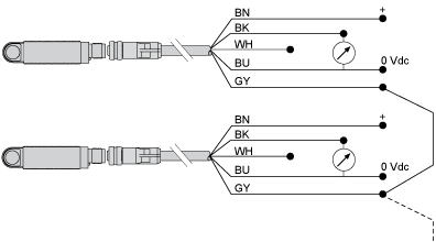
- (1) : Synchronization
- (2) : External setting pushbutton or XXZPB100 remote teach pushbutton.
- (1) : Synchronization
- BN : Brown
- WH : White
- BU : Blue
- BK : Black
- GY : Grey
Performance Curves
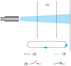
Detection Curve with 100 x 100 mm / 3.94 x 3.94 in. Square Target
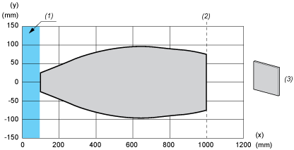
- (x) Target distance
- (y) Detection limit
- (1) : Blind zone: 105 mm
- (2) : Sn max.
- (3) : 100 x 100 mm / 3.94 x 3.94 in. stainless steel plate
Performance Curves
Detection Curve with Round Bar
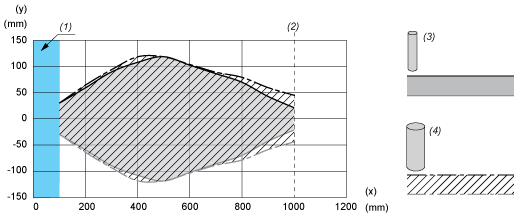
- (x) Target distance
- (y) Detection limit
- (1) : Blind zone: 105 mm
- (2) : Sn max.
- (3) : 100 x 100 mm / 3.94 x 3.94 in. stainless steel plate
- (x) Target distance
- (y) Detection limit
- (1) : Blind zone: 105 mm
- (2) : Sn max.
- (3) : Ø 10 mm / 0.394 in. stainless steel cylinder
- (4) : Ø 25 mm / 0.984 in. stainless steel cylinder
Operating Diagrams Settings with Teach Procedure
Window Mode
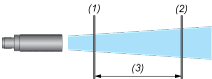
- (1) : Near limit
- (2) : Far limit
- (3) : Sensing window
Operating Diagrams Settings with Teach Procedure
Reflex Mode
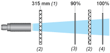
- (1) : Near limit
- (2) : Far limit
- (3) : Sensing window
- (1) : In reflex mode, the position of the reflector must be at least 315 mm away from the sensor.
- (2) : Reflector
- (3) : Near limit
- (4) Far limit
Operating Diagrams Settings with Teach Procedure
Proximity Mode

- (1) : Near limit
- (2) : Far limit
- (3) : Sensing window
- (1) : In reflex mode, the position of the reflector must be at least 315 mm away from the sensor.
- (2) : Reflector
- (3) : Near limit
- (4) Far limit
- (1) : Switch point
Operating Diagrams Settings with Teach Procedure
Pump/Hysteresis Mode

- (1) : Near limit
- (2) : Far limit
- (3) : Sensing window
- (1) : In reflex mode, the position of the reflector must be at least 315 mm away from the sensor.
- (2) : Reflector
- (3) : Near limit
- (4) Far limit
- (1) : Switch point
- (1) : Adjustable detection zone
- (2) : Output activated
- (3) : Output deactivated
- (4) NO output
Operating Diagrams Settings with Teach Procedure
- (1) : Near limit
- (2) : Far limit
- (3) : Sensing window
- (1) : In reflex mode, the position of the reflector must be at least 315 mm away from the sensor.
- (2) : Reflector
- (3) : Near limit
- (4) Far limit
- (1) : Switch point
- (1) : Adjustable detection zone
- (2) : Output activated
- (3) : Output deactivated
- (4) NO output
- (1) : Adjustable detection zone
- (2) : Output activated
- (3) : Output deactivated
- (4) NO output
Expand all
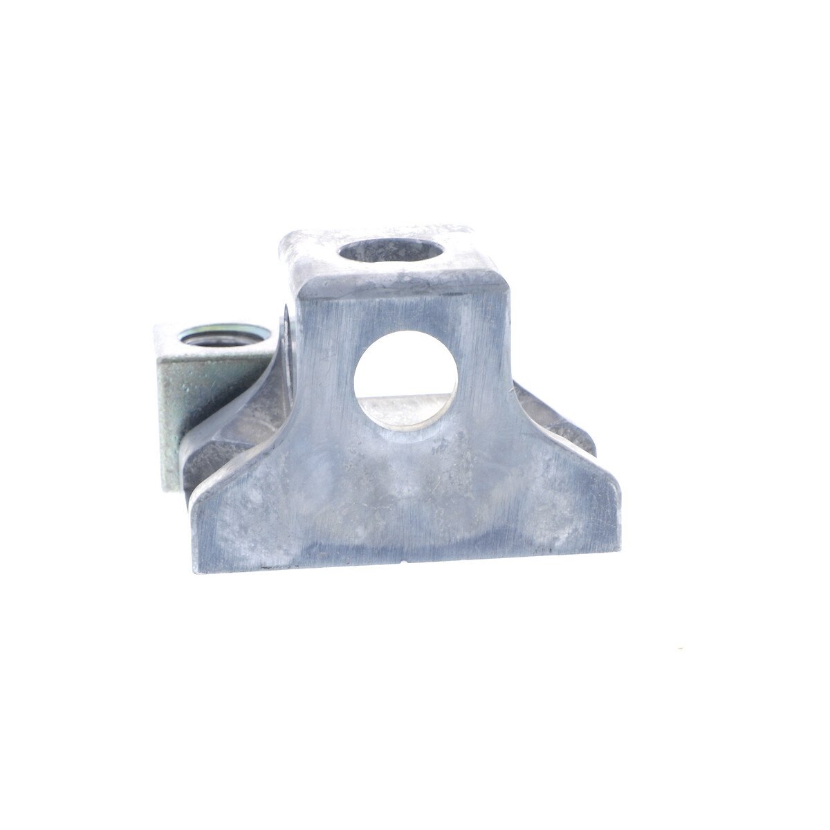
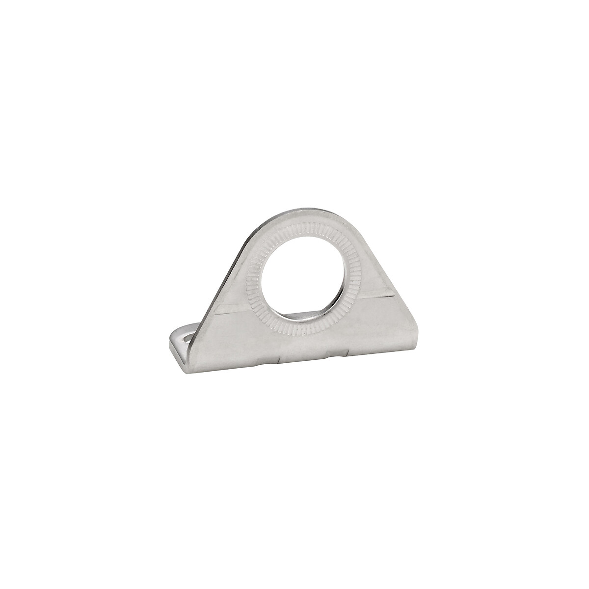
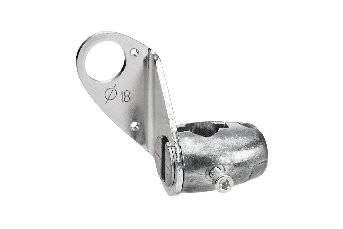
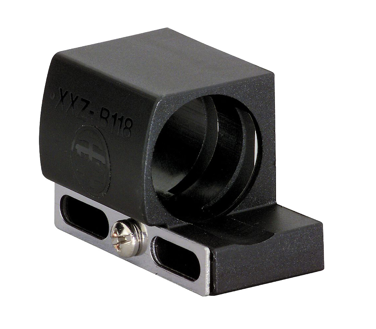
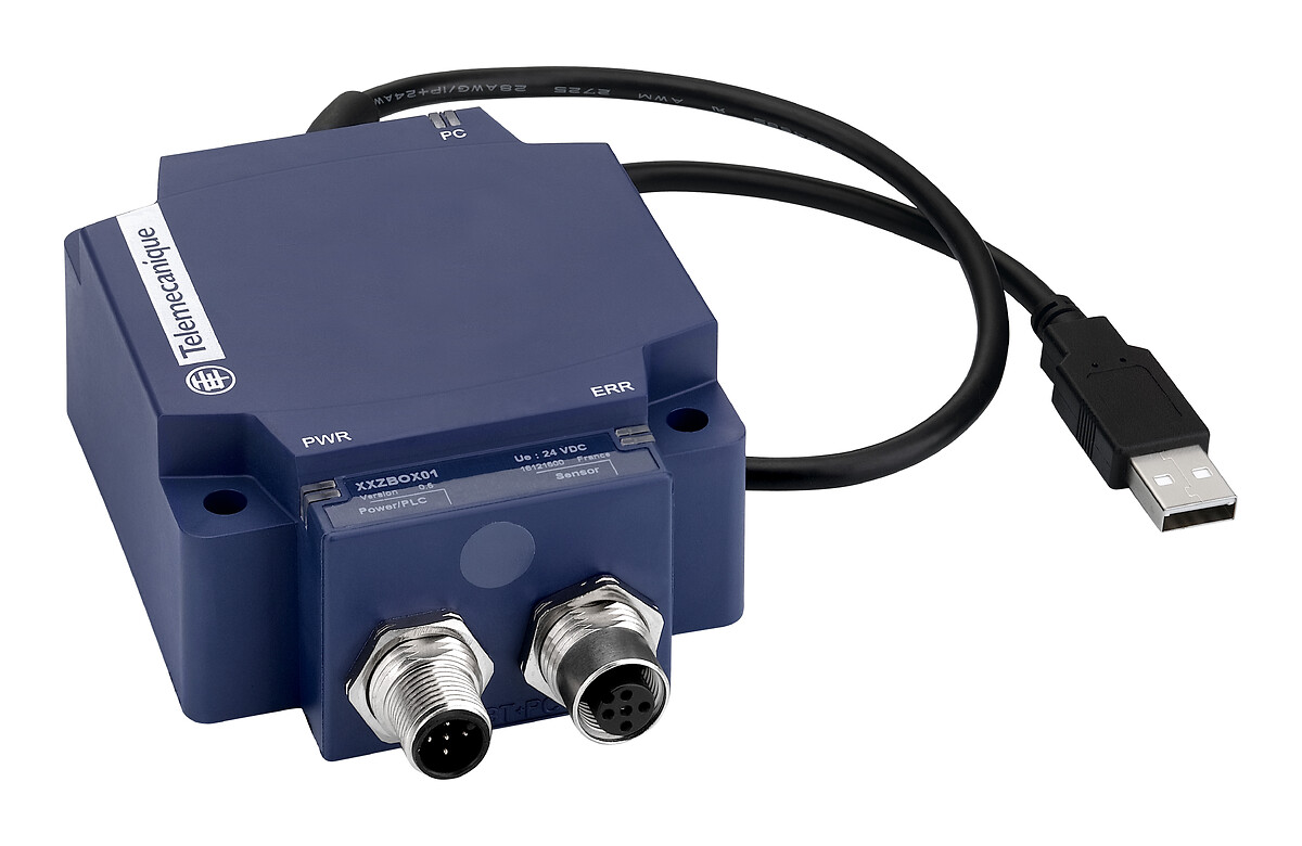
Related products & accessories

Back to top