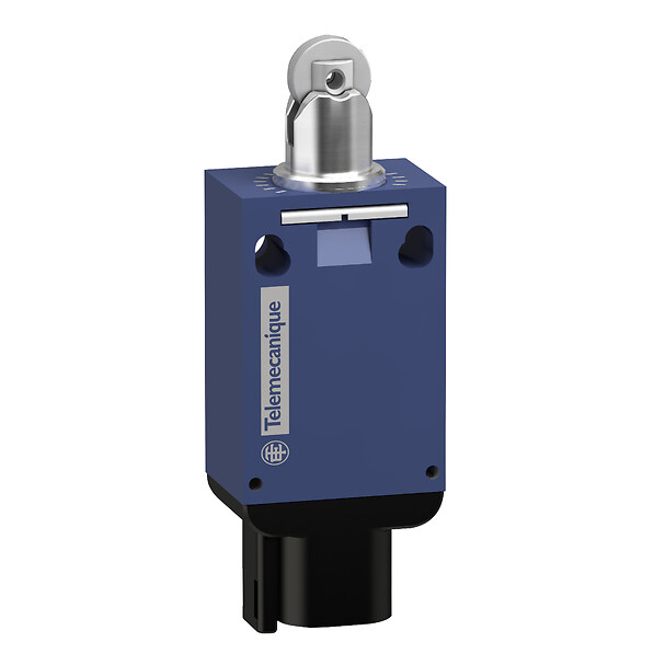
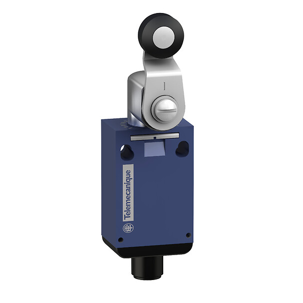
XCMV2110M12
Limit switch, Limit switches XC Standard, XCMD, metal end plunger, 1NC+1 NO, snap, M12

COMMERCIALISED
Expand all
Datasheet
Range of product
Telemecanique Limit switches XC Standard
Series name
Standard format
Product or component type
Limit switch
Device short name
XCMD
Sensor design
Miniature
Body type
Plug-in body
Head type
Plunger head
Material
Metal
Body material
Zamak
Head material
Zamak
Fixing mode
By the body
Movement of operating head
Linear
Type of operator
Spring return plunger metal
Type of approach
Lateral approach, 2 directions
Contacts type and composition
1 NC + 1 NO
Contact operation
Snap action
Switch actuation
By 30° cam
Electrical connection
Male connector M12, 4 pins
Contacts insulation form
Zb
Positive opening
With
Resistance across terminals
25 mOhm conforming to IEC 60255-7 category 3
Shock resistance
25 gn for 18 ms conforming to IEC 60068-2-27
Vibration resistance
5 gn (f= 10-500 Hz) conforming to IEC 60068-2-6
IP degree of protection
IP66 conforming to IEC 60529, IP67 conforming to IEC 60529, IP69 conforming to IEC 60529
IK degree of protection
IK04 conforming to EN 62262
Electrical shock protection class
Class III conforming to IEC 61140, class III conforming to NF C 20-030
Protective treatment
TC
Product certifications
CCC
cURus
cURus
Standards
CSA C22.2 No 14
EN/IEC 60204-1
EN/IEC 60947-5-1
UL 508
EN/IEC 60204-1
EN/IEC 60947-5-1
UL 508
Unit type of package 1
PCE
Number of units in package 1
1
Package 1 height
3 CENTIMETER
Package 1 width
7 CENTIMETER
Package 1 length
17 CENTIMETER
Package 1 weight
0.09 KILOGRAM
Unit type of package 2
S02
Number of units in package 2
50
Package 2 height
15 CENTIMETER
Package 2 width
30 CENTIMETER
Package 2 length
40 CENTIMETER
Package 2 weight
4.664 KILOGRAM
Indivisible sale quantity
1
California proposition 65
WARNING: This product can expose you to chemicals including: Diisononyl phthalate (DINP), which is known to the State of California to cause cancer, and Di-isodecyl phthalate (DIDP), which is known to the State of California to cause birth defects or other reproductive harm. For more information go to www.P65Warnings.ca.gov
Expand all
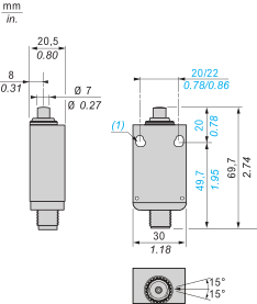
Technical Drawings
Dimensions
Connections and Schema
Wiring Diagram

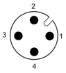
Connections and Schema
M12 Connector
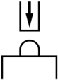
Technical Description
Characteristics of Actuation
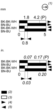
Technical Description
Functional Diagram, Travel Distance
Expand all
Documents & Downloads
Document name
Date
Size
2024-07-15
68162797
2024-07-31
62841900
Document name
Date
Size
2023-03-01
1756416
2024-04-01
6172346
2018-07-01
317798
Document name
Date
Size
2024-07-18
116631
2024-07-18
16722
2024-07-18
18382
2024-07-18
19772
2024-07-18
20405
2024-07-18
21239
2024-07-18
21239
2024-07-18
22522
2024-07-18
22689
2024-07-18
22691
2024-07-18
29608
2024-07-18
30967
2024-07-18
49502
2024-07-18
49972
2024-07-18
64016
2024-07-18
926089
Document name
Date
Size
2026-04-14
109562
2026-04-13
108798
Document name
Date
Size
Expand all
Related products & accessories

Back to top