XCRA51
Limit switch XCRA, square rod lever 6 mm, spring return

COMMERCIALISED
Expand all
Datasheet
Range of product
OsiSense XC
Series name
Special format
Product or component type
Limit switch
Device short name
XCR
Product specific application
For hoisting and mechanical handling applications
ETIM classification
ETIM 9 - EC000030 - End switch
Body type
Fixed
Head type
Rotary head
Material
Metal
Body material
Zinc alloy
Fixing mode
By the body
Movement of operating head
Rotary
Type of operator
Spring return rod lever metal square rod 6 mm
Switch actuation
By any moving part
Type of approach
Lateral approach, 2 directions
Number of poles
4
Product certifications
CCC
CSA
CSA
Standards
CSA C22.2 No 14
IEC 60204-1
IEC 60947-5-1
NF C 79-130
IEC 60204-1
IEC 60947-5-1
NF C 79-130
Indivisible sale quantity
1
Mechanical durability
10000000 cycles
Minimum torque for tripping
0.45 N.m
Minimum actuation speed
6 m/mn
Maximum actuation speed
1.5 m/s
Cable entry
1 entry tapped for Pg 13.5 cable gland, cable outer diameter: 9-12 mm conforming to NF C 68-300
Contact code designation
A300, AC-15 (Ue = 240 V), Ie = 3 A conforming to IEC 60947-5-1 appendix A, Q300, DC-13 (Ue = 250 V), Ie = 0.27 A conforming to IEC 60947-5-1 appendix A
Electrical durability
5000000 cycles, DC-13, inductive load type, 120 V, 4 W, operating rate <60 cyc/mn, load factor: 0.5 conforming to IEC 60947-5-1 appendix C, 5000000 cycles, DC-13, inductive load type, 24 V, 7 W, operating rate <60 cyc/mn, load factor: 0.5 conforming to IEC 60947-5-1 appendix C, 5000000 cycles, DC-13, inductive load type, 48 V, 10 W, operating rate <60 cyc/mn, load factor: 0.5 conforming to IEC 60947-5-1 appendix C
Electrical connection
Screw-clamp terminals, clamping capacity: 1 x 0.5...2 x 2.5 mm²
Positive opening
With, conforming to IEC 60947-5-1 Annex K
Positive opening minimum torque
0.75 N.m
Contact block per direction [control circuit]
2 per direction
Contacts insulation form
Zb
Contacts type and composition
2 x (1 NC + 1 NO)
Terminals description ISO n°1
(13-14)NO
(21-22)NC
(21-22)NC
Contact operation
Slow-break, break before make
[Uimp] rated impulse withstand voltage
6 kV conforming to IEC 60664, 6 kV conforming to IEC 60947-1
[Ui] rated insulation voltage
300 V conforming to UL 508, 500 V (pollution degree 3) conforming to IEC 60947-1, 500 V (pollution degree 3) conforming to VDE 0110, 300 V conforming to CSA C22.2 No 14
Overvoltage category
Class I conforming to IEC 61140, class I conforming to NF C 20-030
Resistance across terminals
25 MOhm conforming to IEC 60255-7 category 3
Short-circuit protection
10 A cartridge fuse, type gG
Width
85 mm
Depth
75 mm
Product weight
1.11 kg
IP degree of protection
IP54 conforming to IEC 60529
Ambient air temperature for operation
-25…70 °C
Ambient air temperature for storage
-40…70 °C
Shock resistance
68 gn conforming to IEC 60068-2-27
Vibration resistance
9 gn (f= 10-500 Hz) conforming to IEC 60068-2-6
Protective treatment
TC
California proposition 65
WARNING: This product can expose you to chemicals including: Diisononyl phthalate (DINP), which is known to the State of California to cause cancer, and Di-isodecyl phthalate (DIDP), which is known to the State of California to cause birth defects or other reproductive harm. For more information go to www.P65Warnings.ca.gov
Warranty
18 months
Country of origin
FR (France)
Unit type of package 1
PCE
Number of units in package 1
1
New Package 1 GTIN-13
3666916049723
Package 1 height
8 cm
Package 1 width
10.5 cm
Package 1 length
20.5 cm
Package 1 weight
1.11 kg
Unit type of package 2
S02
Number of units in package 2
4
New Package 2 GTIN 14
13666916049720
Package 2 height
15 cm
Package 2 width
30 cm
Package 2 length
40 cm
Package 2 weight
4.631 kg
Unit type of package 3
CAR
Number of units in package 3
1
New Package 3 GTIN 14
23666916049727
Package 3 height
8 cm
Package 3 width
20.5 cm
Package 3 length
10.5 cm
Package 3 weight
1.044 kg
Expand all
Technical Drawings
Dimensions

- (1) 1 tapped entry for n° 13 cable gland.
- (2) Rod length: 200 mm.
Wiring Diagram
Two 2-pole NC + NO Break Before Make, Slow Break
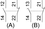
- (A) 1 contact
- (B) 2 contact
Functionnal Diagram

- (P) Positive opening point
- (A) 1st contact
- (B) 2nd contact
- (1) NC contact with positive opening operation
- (2) Closed
- (3) Open
- (4) Tripping
- (5) Resetting
Expand all
Documents & Downloads
Document name
Date
Size
2025-01-16
10778833
2025-01-10
10641190
Document name
Date
Size
2005-01-13T00:00:00.000Z
189944
2005-01-13
20178
2005-01-13
213752
2005-01-13T00:00:00.000Z
261326
2005-01-13
413190
2005-01-13T00:00:00.000Z
448886
2005-01-13
47562
2005-01-13
478454
2005-01-13T00:00:00.000Z
672901
2005-01-13
82216
2024-07-18T00:00:00.000Z
21303
2024-07-18T00:00:00.000Z
230134
2024-07-18T00:00:00.000Z
23069
2024-07-18T00:00:00.000Z
23163
2024-07-18T00:00:00.000Z
23287
2024-07-18T00:00:00.000Z
23768
2024-07-18T00:00:00.000Z
23865
2024-07-18T00:00:00.000Z
24633
2024-07-18T00:00:00.000Z
34106
2024-07-18T00:00:00.000Z
36027
2024-07-18T00:00:00.000Z
36086
2024-07-18T00:00:00.000Z
37091
2024-07-18T00:00:00.000Z
37204
2024-07-18T00:00:00.000Z
461163
Document name
Date
Size
2026-08-20
275145
2026-04-14
109573
2026-04-13
108811
Document name
Date
Size
2024-10-15
253147
2024-03-19
228277
2024-03-19
190308
Document name
Date
Size
2024-07-26
1766665
2017-11-16
2626190
Back to top
