XCSRC31MM12
Preventa RFID safety switch, Telemecanique Safety switches XCS, Standalone model EDM+Manual Start 2 new re pairing enabled

COMMERCIALISED
Expand all
Datasheet
Range of product
Telemecanique Safety switches XCS
Product or component type
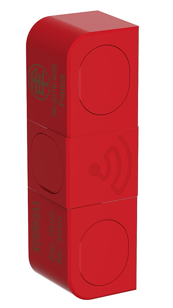
Preventa RFID safety switch
Component name
XCSRC
Design
Rectangular, standard
Size
Transponder: 50 x 15 x 15 mm, reader: 108.3 x 30 x 15 mm
Material
Valox
Electrical connection
1 male connector
Connector type
M12 male
Type of output stage
Solid-state, PNP
Safety outputs
2 NO
Local signalling
Green, orange and red 2 multi-colour LEDs
Approach directions
3 directions-transponder with rotary sensing face
[Ue] rated operational voltage
24 V DC (- 20...10 %)SELV or PELV conforming to IEC 60204-1
Protection type
Short-circuit protection
Switching capacity in mA
400 mA
Switching frequency
<= 0.5 Hz
Discordance time
120 ms
Response time
250 ms typical
Delay first up
5 SECOND
Tightening torque
< 1.5 N.m
Standards
IEC 60947-5-2
IEC 60947-5-3
ISO 14119
IEC 60947-5-3
ISO 14119
Product certifications
CSA 22-2
E2
Ecolab
FCC
IC
RCM
TÜV
E2
Ecolab
FCC
IC
RCM
TÜV
Marking
CE
cULus
EAC
FCC
IC
RCM
TÜV
cULus
EAC
FCC
IC
RCM
TÜV
Safety level
SIL 3 conforming to IEC 61508, SILCL 3 conforming to IEC 62061, PL = e conforming to ISO 13849-1, category 4 conforming to ISO 13849-1
Safety reliability data
PFHD = 5E-10/h conforming to IEC 62061, PFHD = 5E-10/h conforming to ISO 13849-1
Vibration resistance
10 gn (f= 10-150 Hz) conforming to IEC 60068-2-6
Shock resistance
30 gn for 11 ms conforming to IEC 60068-2-27
Electrical shock protection class
Class III conforming to IEC 61140
IP degree of protection
IP65 conforming to IEC 60529, IP66 conforming to IEC 60529, IP67 conforming to IEC 60529, IP69K conforming to DIN 40050
Unit type of package 1
PCE
Number of units in package 1
1
Package 1 height
2 CENTIMETER
Package 1 width
11 CENTIMETER
Package 1 length
15 CENTIMETER
Package 1 weight
0.103 KILOGRAM
Unit type of package 2
S01
Number of units in package 2
12
Package 2 height
15 CENTIMETER
Package 2 width
15 CENTIMETER
Package 2 length
40 CENTIMETER
Package 2 weight
1.425 KILOGRAM
Indivisible sale quantity
1
California proposition 65
WARNING: This product can expose you to chemicals including: Diisononyl phthalate (DINP), which is known to the State of California to cause cancer, and Di-isodecyl phthalate (DIDP), which is known to the State of California to cause birth defects or other reproductive harm. For more information go to www.P65Warnings.ca.gov
Expand all
Technical Drawings
Dimensions
Connections
M12 Connector, 8-pin
- (1) + 24 VDC
- (2) OSSD2
- (3) 0 VDC
- (4) OSSD1
- (5) EDM_ST_1
- (6) EDM_ST_2
- (7) NC (Not connected)
- (8) NC (Not connected)
Connections
Wiring Diagram
- (1) Power Supply
- (2) Reader
- (3) Transponder
- (4) 1 A max.
- (5) Restart
- (6) Use of arc suppressors for KM1 and KM2 is recommended.
- (7) Power circuit
Mounting and Clearance
Mounting and Clearance
Face to Face Mounting (Preferred Configuration)
- e min. > 2 mm. (e: recommended minimum mounting distance between transponder and reader)
- d : Detection limit
Mounting and Clearance
Side by Side Mounting
- e: Recommended minimum mounting distance between transponder and reader.
Mounting and Clearance
Minimum Mounting Clearances between Safety Switches
Detection Curves
Face to Face Mounting (Preferred Configuration)
- Sar: Assured release distance
- Sao: Assured operating distance
- (1) Recommended minimum mounting distance between transponder and reader.
Detection Curves
- Sar: Assured release distance
- Sao: Assured operating distance
- (1) Recommended minimum mounting distance between transponder and reader.
- Sar: Assured release distance
- Sao: Assured operating distance
- (1) Recommended minimum mounting distance between transponder and reader.
Detection Curves
Side by Side Mounting
- Sar: Assured release distance
- Sao: Assured operating distance
- (1) X=0 for X<0
- (2) X=0 for X>0
- (3) Recommended minimum mounting distance between transponder and reader.
Detection Curves
- Sar: Assured release distance
- Sao: Assured operating distance
- (1) X=0 for X<0
- (2) X=0 for X>0
- (3) Recommended minimum mounting distance between transponder and reader.
- Sar: Assured release distance
- Sao: Assured operating distance
- (1) X=0 for X<0
- (2) X=0 for X>0
- (3) Recommended minimum mounting distance between transponder and reader.
Expand all
Documents & Downloads
Document name
Date
Size
2024-10-31
31713778
2024-10-31
30971574
Document name
Date
Size
2017-03-01
2329593
Document name
Date
Size
Document name
Date
Size
2024-07-18
142014
2024-07-18
20336
2024-07-18
20889
2024-07-18
22101
2024-07-18
22746
2024-07-18
22807
2024-07-18
24866
2024-07-18
252450
2024-07-18
30697
2024-07-18
3085472
2024-07-18
31815
2024-07-18
32697
2024-07-18
50752
2024-07-18
74348
2024-07-18
79974
Document name
Date
Size
2026-04-14
110201
2026-04-13
108959
Document name
Date
Size
2024-06-27
191465
Document name
Date
Size
Document name
Date
Size
2026-01-26
4343561
2026-01-26
13816670
2026-01-26
3906030
2026-01-26
3971241
2026-01-26
5294784
Expand all
Related products & accessories

Back to top