XMLC020B2S11
Pressure switch, XMLC, pressure range 20 bar, adjustable scale, 2CO, 2 thresholds

COMMERCIALISED
Expand all
Datasheet
Range of product
Telemecanique Pressure sensors XM
Pressure sensor type
Electromechanical pressure sensor
Product or component type
Electromechanical pressure sensor
Device short name
XMLC
Product specific application
Not applicable
ETIM classification
ETIM 9 - EC000243 - Pressure switch
Enclosure material
Zinc alloy
Materials in contact with fluid
Brass
FPM, FKM
FPM, FKM
Pressure switch type of operation
Regulation between 2 thresholds
Operating position
Any position
Pressure sensor size
20 Bar
Maximum permissible accidental pressure
45 Bar
Maximum permissible pressure - per cycle
25 Bar
Destruction pressure
90 Bar
Pressure actuator
Diaphragm
Possible differential maximum at high setting
11 Bar
Controlled fluid
Air (0-160 °C), fresh water (0-160 °C), hydraulic oil (0-160 °C)
Fluid connection type
G 1/4 (female) conforming to ISO 228
Local display
With
AWG gauge
AWG 20...AWG 14
Scale type
Adjustable differential
Setting
External
Product certifications
CSA
UL
UL
Standards
CE
CSA C22.2 No 14
IEC 60947-5-1
UL 508
CSA C22.2 No 14
IEC 60947-5-1
UL 508
Range compatibility
TE PRESSURE SSRS XM
Indivisible sale quantity
1
Mechanical durability
5000000 cycles
Cable entry
Cable gland 9-13 mm
Repeat accuracy
2 %
Electrical connection
Screw-clamps terminals, 1 x 0.5...2 x 2.5 mm²
Electrical circuit type
Control circuit
Contacts type and composition
2 C/O
Contacts material
Silver contacts
Terminals description ISO n°1
(13-14-11-12)OF
Terminals description ISO n°2
(23-24-21-22)OF
Auxiliary contacts operation
Simultaneous, snap action
Operating rate
120 cyc/mn
[Uimp] rated impulse withstand voltage
6 kV conforming to IEC 60947-1
[Ui] rated insulation voltage
300 V conforming to UL 508, 500 V conforming to IEC 60947-1, 300 V conforming to CSA C22.2 No 14
[In] rated current
3 A, B300, AC-15 (Ue = 120 V) conforming to IEC 60947-5-1, 1.5 A, B300, AC-15 (Ue = 240 V) conforming to IEC 60947-5-1, 0.1 A, R300, DC-13 (Ue = 250 V) conforming to IEC 60947-5-1
Resistance across terminals
25 mOhm conforming to IEC 255-7 category 3, 25 mOhm conforming to NF C 93-050 method A
Electrical shock protection class
Class I conforming to IEC 1140, class I conforming to IEC 536, class I conforming to NF C 20-030
Short-circuit protection
10 A cartridge fuse, type gG (gl)
Adjustable range of switching point on rising pressure
1.3000…20.0000 bar
Adjustable range of switching point on falling pressure
0.6000…19.0000 bar
Terminal block type
8 terminals
Possible differential minimum at low setting
0.7 bar (+/- 0.2 bar)
Possible differential minimum at high setting
1 bar (+/- 0.2 bar)
Height
113 mm
Width
46 mm
Depth
85 mm
Product weight
0.685 kg
IP degree of protection
IP66 conforming to IEC 60529
Ambient air temperature for operation
-25…70 °C
Ambient air temperature for storage
-40…70 °C
Shock resistance
50 gn conforming to IEC 60068-2-27
Vibration resistance
4 gn conforming to IEC 60068-2-6 (f = 30-500 Hz)
Protective treatment
TC standard version
California proposition 65
WARNING: This product can expose you to chemicals including: Diisononyl phthalate (DINP), which is known to the State of California to cause cancer, and Di-isodecyl phthalate (DIDP), which is known to the State of California to cause birth defects or other reproductive harm. For more information go to www.P65Warnings.ca.gov
Warranty
18 months
Country of origin
CZ (Czech Republic)
MA (Morocco)
MA (Morocco)
Unit type of package 1
PCE
Number of units in package 1
1
New Package 1 GTIN-13
3666916026380
Package 1 height
6 cm
Package 1 width
15 cm
Package 1 length
10.7 cm
Package 1 weight
0.685 kg
Unit type of package 2
S01
Number of units in package 2
4
New Package 2 GTIN 14
13666916026387
Package 2 height
15 cm
Package 2 width
15 cm
Package 2 length
40 cm
Package 2 weight
3.705 kg
New Package 3 GTIN 14
23666916026384
Expand all
Technical Drawings
Dimensions
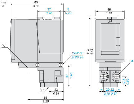
- (1) 1 fluid entry, tapped G1/4 (BSP female)
- (2) 1 electrical connections entry, tapped Pg 13.5
- Ø : 2 elongated holes Ø 5.2 x 6.7
Wiring Diagram
Terminal Model

Operating Curves

- (y) Rising pressure
- (x) Falling pressure
- 1 : Maximum differential
- 2 : Minimum differential

- (y) Rising pressure
- (x) Falling pressure
- 1 : Maximum differential
- 2 : Minimum differential
- (y) Pressure
- (x) Time
- (1) Adjustable value
- PH : High point
- PB : Below point
Expand all
Documents & Downloads
Document name
Date
Size
2024-02-07
16935225
Document name
Date
Size
2024-07-18T00:00:00.000Z
18908
2024-07-18T00:00:00.000Z
20184
2024-07-18T00:00:00.000Z
20729
2024-07-18T00:00:00.000Z
21112
2024-07-18T00:00:00.000Z
21273
2024-07-18T00:00:00.000Z
22055
2024-07-18T00:00:00.000Z
22456
2024-07-18T00:00:00.000Z
23205
2024-07-18T00:00:00.000Z
23450
2024-07-18T00:00:00.000Z
23893
2024-07-18T00:00:00.000Z
245773
2024-07-18T00:00:00.000Z
26063
2024-07-18T00:00:00.000Z
28582
2024-07-18T00:00:00.000Z
29206
2024-07-18T00:00:00.000Z
53828
Document name
Date
Size
2026-08-20
283550
2026-04-14
109452
2026-04-14
108701
Document name
Date
Size
2024-03-01
874020
Document name
Date
Size
2023-09-13
816531
Document name
Date
Size
XMLA/B/C/D… pressure and vacuum switches for control circuits - CMim declaration of conformity (pdf)
2024-10-15
281091
Back to top
