XMLD160D1S13
pressure switch XMLD 160 bar - 2 stages fixed scale - 2 C/O

COMMERCIALISED
Expand all
Datasheet
Range of product
Telemecanique Pressure sensors XM
Product or component type
Electromechanical pressure sensor
Pressure sensor type
Electromechanical pressure sensor
Device short name
XMLD
Controlled fluid
Hydraulic oil (0-160 °C)
Fluid connection type
1/4" - 18 NPTF (female)
Electrical connection
Screw-clamps terminals, 1 x 0.5...2 x 2.5 mm²
AWG gauge
AWG 20...AWG 14
Cable entry
Cable gland
Contacts type and composition
2 C/O snap action, silver contacts, 2 C/O staggered, silver contacts
Product specific application
Dual stage
Pressure switch type of operation
Detection of 2 single thresholds
Electrical circuit type
Control circuit
Scale type
Fixed differential
Local display
Without
Pressure actuator
Piston
Materials in contact with fluid
Brass
FPM, FKM
PTFE
steel
FPM, FKM
PTFE
steel
Enclosure material
Zinc alloy
Terminal block type
8 terminals
Operating rate
60 cyc/mn
Resistance across terminals
25 mOhm conforming to IEC 255-7 category 3, 25 mOhm conforming to NF C 93-050 method A
Setting
External
Standards
CE
CSA C22.2 No 14
IEC 60947-5-1
UL 508
CSA C22.2 No 14
IEC 60947-5-1
UL 508
Product certifications
CSA
UL
UL
Protective treatment
TC standard version
Operating position
Any position
Vibration resistance
4 gn conforming to IEC 60068-2-6 (f = 30-500 Hz)
Shock resistance
50 gn conforming to IEC 60068-2-27
Electrical shock protection class
Class I conforming to IEC 1140, class I conforming to IEC 536, class I conforming to NF C 20-030
IP degree of protection
IP66 conforming to IEC 60529
Unit type of package 1
PCE
Number of units in package 1
1
Package 1 height
6 CENTIMETER
Package 1 width
10.5 CENTIMETER
Package 1 length
14 CENTIMETER
Package 1 weight
1.05 KILOGRAM
Indivisible sale quantity
1
California proposition 65
WARNING: This product can expose you to chemicals including: Diisononyl phthalate (DINP), which is known to the State of California to cause cancer, and Di-isodecyl phthalate (DIDP), which is known to the State of California to cause birth defects or other reproductive harm. For more information go to www.P65Warnings.ca.gov
Expand all
Technical Drawings
Dimensions
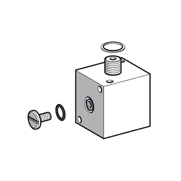
- (1) 1 fluid entry, tapped 1/4" NPTF
- (2) 1 electrical connections entry, tapped 1/2" NPT
- Ø : 2 elongated holes Ø 5.2 x 6.7
Wiring Diagram
Terminal Model
- (a) Contact 1
- (b) Contact 2
Operating Curves
High Setting Tripping Points of Contacts 1 and 2
- (y) PH2 setting (rising pressure)
- (x) PH1 setting (rising pressure)
- 1 : Maximum differential
- 2 : Minimum differential
Operating Curves
Natural Differential of Contacts 1 and 2
- (y) PH2 setting (rising pressure)
- (x) PH1 setting (rising pressure)
- 1 : Maximum differential
- 2 : Minimum differential
- (y) Rising pressure
- (x) Falling pressure
- EF : Contact 1
- GH : Contact 2
Natural Differential of Contacts 1 and 2
- (y) PH2 setting (rising pressure)
- (x) PH1 setting (rising pressure)
- 1 : Maximum differential
- 2 : Minimum differential
- (y) Rising pressure
- (x) Falling pressure
- EF : Contact 1
- GH : Contact 2
- (y) Pressure
- (x) Time
- (1) Adjustable value
- (2) Non adjustable value
- PH : High point
- PB : Below point
Expand all
Documents & Downloads
Document name
Date
Size
2026-04-15
17217675
Document name
Date
Size
2026-04-14
109460
2026-04-14
108686
Document name
Date
Size
Document name
Date
Size
2023-09-13
816531
Document name
Date
Size
XMLA/B/C/D… pressure and vacuum switches for control circuits - CMim declaration of conformity (pdf)
2024-10-15
281091
Back to top