XX218A3PFM12
Ultrasonic sensors XX, ultrasonic sensor cylindrical M18, 2 filling levels, Sn 0.5 m, NO, M12

COMMERCIALISED
Expand all
Datasheet
Range of product
Telemecanique Ultrasonic sensors XX
Sensor type
Ultrasonic sensor
Series name
Application
Sensor name
XX2
Sensor design
Cylindrical M18
Detection system
Diffuse
Material
Plastic
Type of output signal
Discrete
Discrete output function
1 NO
Wiring technique
3-wire
[Us] rated supply voltage
12...24 V DC with reverse polarity protection
Discrete output type
PNP
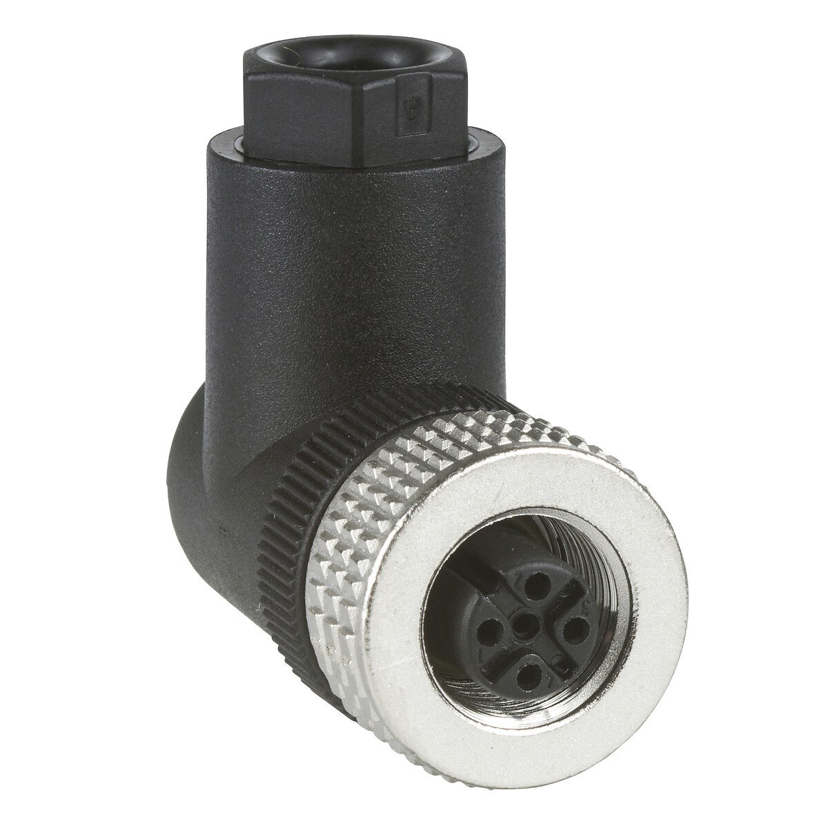
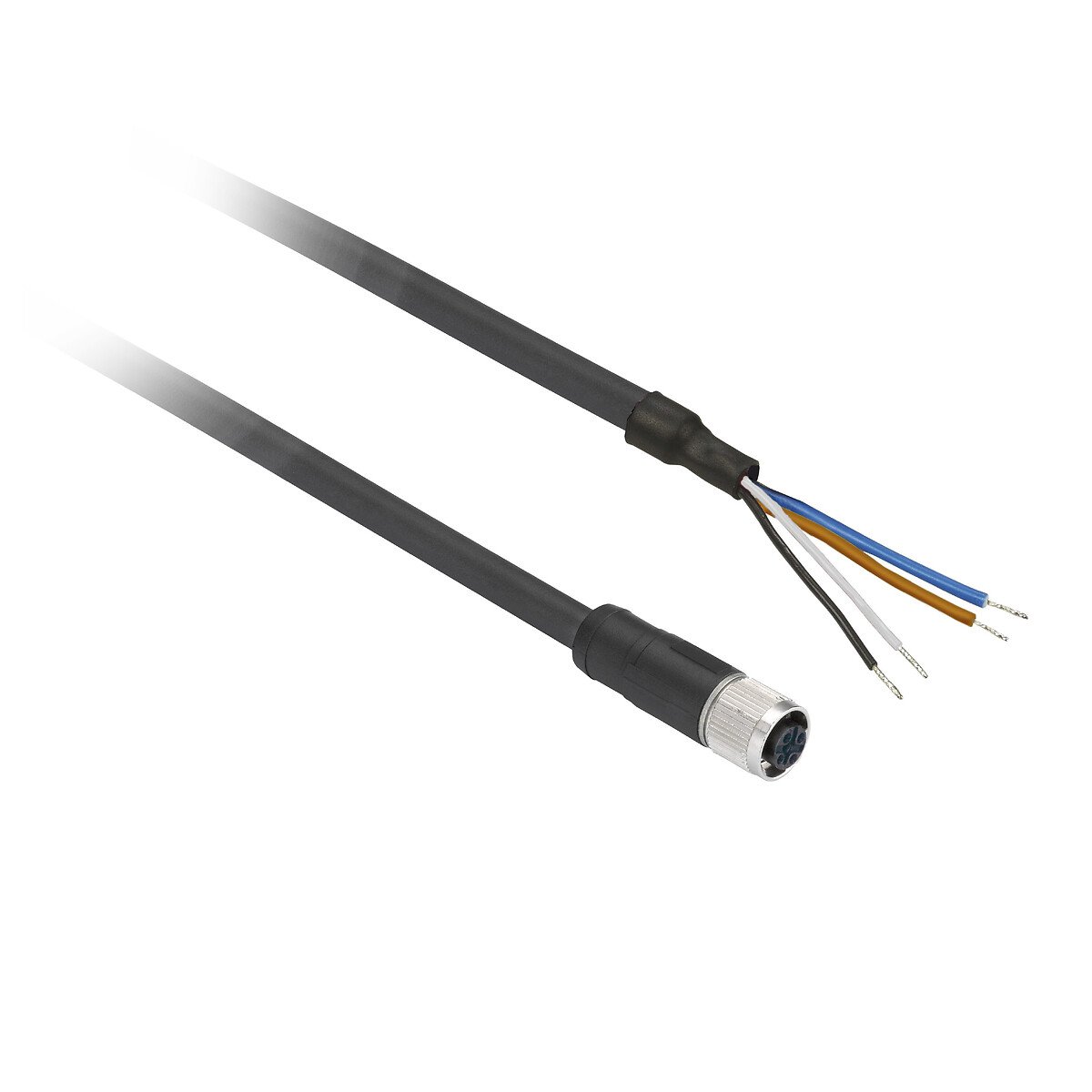
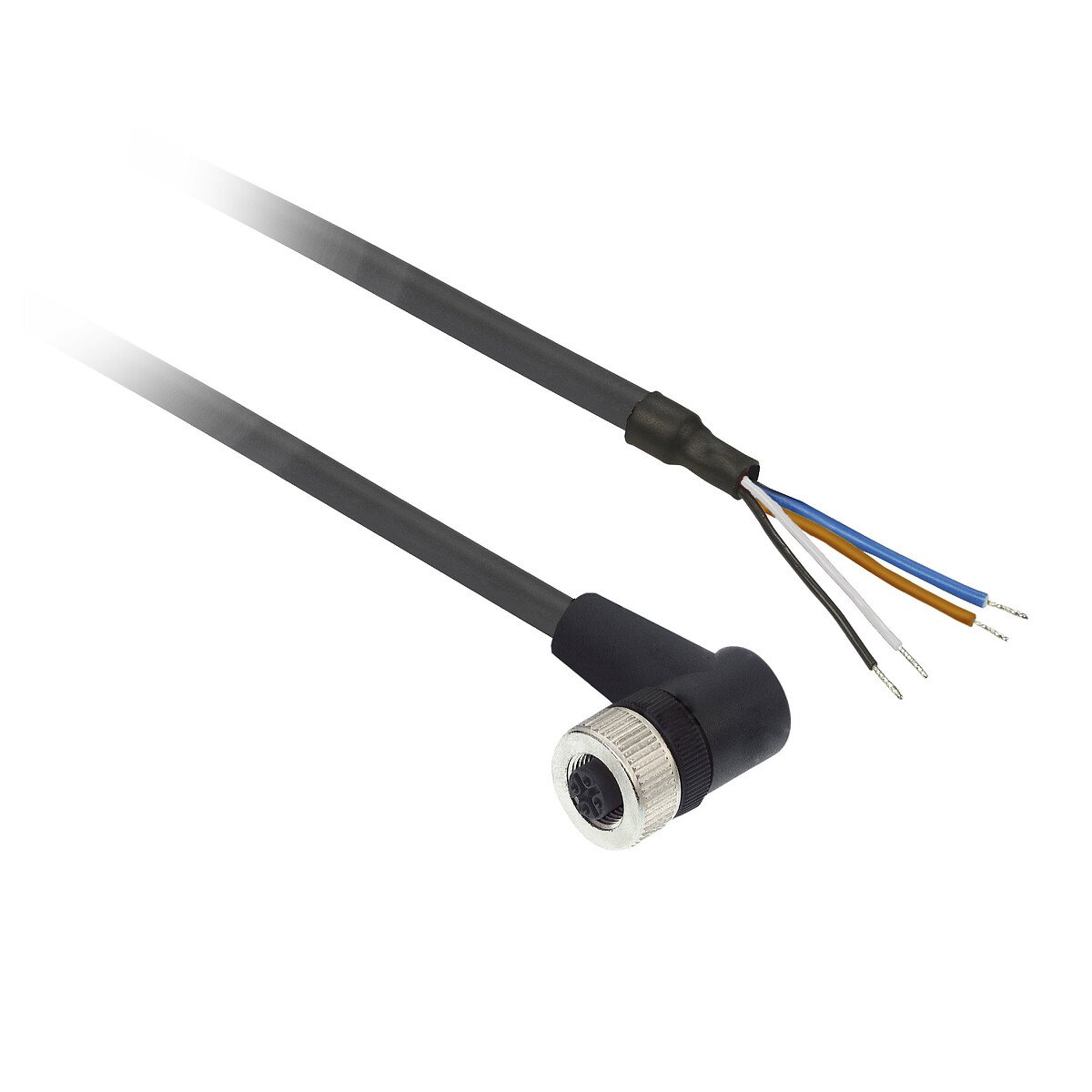
Electrical connection
Male connector M12 4 pins
Product specific application
For 2 filling levels monitoring
Enclosure material
Valox
Front material
Epoxy
Thread type
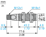
M18 x 1
Voltage drop
1 VOLT
Minimum size of detected object
Cylinder diameter 2.5 mm at 0.15 m
Delay first up
100 MILLISECOND
Current consumption
40 mA
Status LED
Setting-up assistance: 1 LED (dual colour), supply on: 1 LED (green), output state: 1 LED (yellow)
Delay response
15 MILLISECOND
Delay recovery
1000 MILLISECOND
IP degree of protection
IP67 conforming to IEC 60529
Marking
CE
Standards
IEC 60947-5-2
Product certifications
CCSAus
UL
UL
Vibration resistance
+/-1 mm conforming to IEC 60068-2-6 (f = 10-55 Hz)
Shock resistance
30 gn in all 3 axes for 11 ms conforming to IEC 60068-2-27
Unit type of package 1
PCE
Number of units in package 1
1
Package 1 height
4 CENTIMETER
Package 1 width
8.5 CENTIMETER
Package 1 length
8.5 CENTIMETER
Package 1 weight
0.046 KILOGRAM
Unit type of package 3
S02
Number of units in package 3
22
Package 3 height
15 CENTIMETER
Package 3 width
30 CENTIMETER
Package 3 length
40 CENTIMETER
Unit type of package 2
S01
Number of units in package 2
15
Package 2 height
15 CENTIMETER
Package 2 width
15 CENTIMETER
Package 2 length
40 CENTIMETER
Package 2 weight
0.943 KILOGRAM
Indivisible sale quantity
1
California proposition 65
WARNING: This product can expose you to chemicals including: Diisononyl phthalate (DINP), which is known to the State of California to cause cancer, and Di-isodecyl phthalate (DIDP), which is known to the State of California to cause birth defects or other reproductive harm. For more information go to www.P65Warnings.ca.gov
Expand all
Technical Drawings
Dimensions
Minimum Mounting Distances
Side by side

- e : respect the distances indicated on the detection curves
Minimum Mounting Distances
Face to face

- e : respect the distances indicated on the detection curves
- e > 4 x Sn
Wiring Diagram
3-Wire Type

- (1) (+)
- (2) Teach input (WH)
- (3) (-)
- (4) Output
- BN Brown
- WH White
- BU Blue
- BK Black
Curves

- (1) Parallel movement
- (2) Distance
- (3) Blind zone for diffuse sensors.
Operating Curves
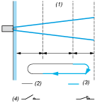
- (1) Adjustable detection zone
- (2) Output deactivated
- (3) Output activated
- (4) NO output
Expand all
Documents & Downloads
Document name
Date
Size
2024-02-07
18903140
2024-02-07
18921683
Document name
Date
Size
2024-04-01
15806982
Document name
Date
Size
2026-04-29
109715
2026-04-29
108822
Document name
Date
Size
Expand all
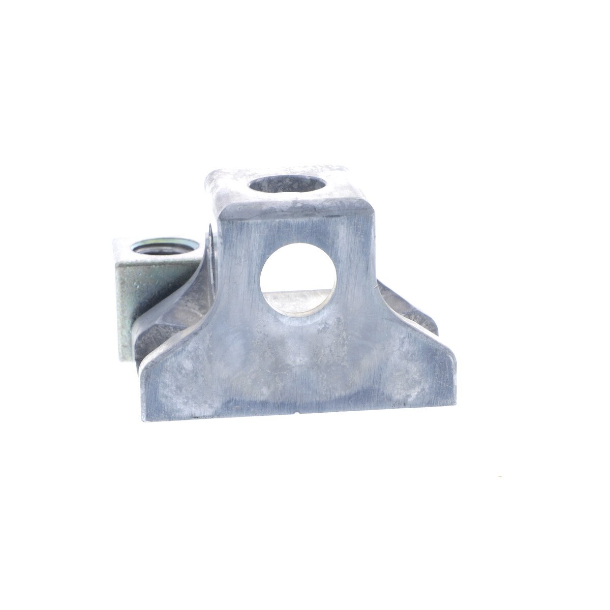
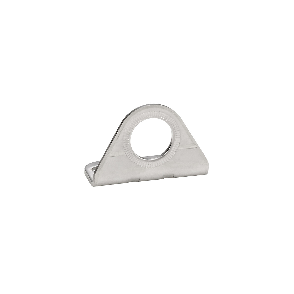
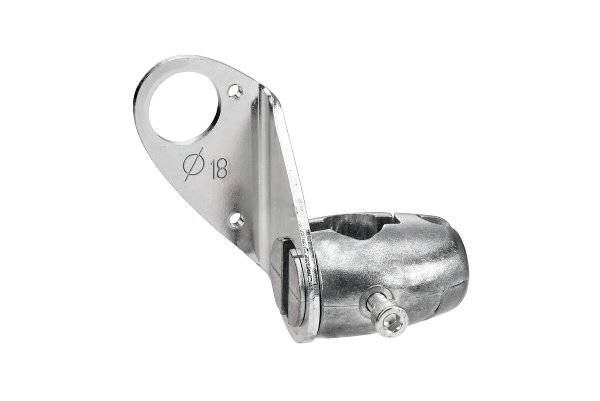
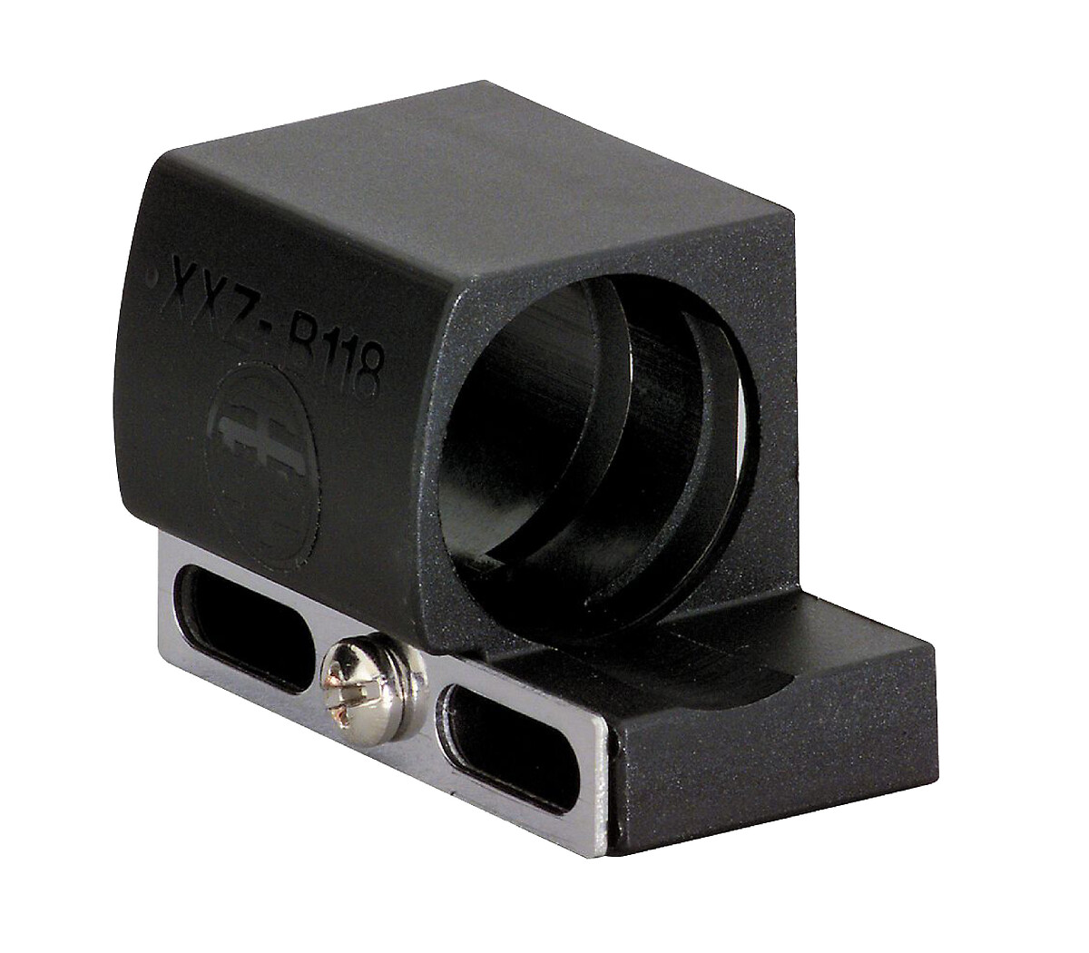
Related products & accessories
Back to top