XCMW115
Wireless limit switch, Limit switches XC Standard, XCMW, plastic roller lever

Commercialised
Expand all
Datasheet
Range of product
Telemecanique Limit switches XC Standard
Series name
Miniature format
Product or component type
Wireless limit switch
Device short name
XCMW
Sensor design
Miniature
Body type
Fixed
Head type
Rotary head
Body material
Plastic
Head material
Metal
Lever material
Metal
Fixing mode
By 2 screws
Type of operator
Spring return roller lever thermoplastic
Switch actuation
By 30° cam
Communication network type
ZigBee green power - 2.4 GHz conforming to IEEE 802.15.4
Type of approach
Lateral approach, 2 directions
Electrical composition code
PW1
Response time
<= 2 ms
Contact operation
Snap action
Operating rate
60 CYCLE_PER_MINUTE
Switching operation per year
3600
Electromagnetic compatibility
Radiated emission, immunity for industrial environments, susceptibility to electromagnetic fields - test level: 3 V/m (80...2700 MHz, distance = 20 m), susceptibility to electromagnetic fields - test level: 10 V/m (80...2000 MHz), electrostatic discharge immunity test - test level: 6 kV (on contact (on metal parts)), electrostatic discharge immunity test - test level: 8 kV (in free air (in insulating parts))
Shock resistance
50 gn for 11 ms conforming to IEC 60068-2-27
Vibration resistance
25 gn (f= 10-500 Hz) conforming to IEC 60068-2-6, +/- 10 mm (f= 2-11 Hz) conforming to IEC 60068-2-6
IP degree of protection
IP65 conforming to IEC 60529
IK degree of protection
IK04 conforming to IEC 62262
Directives
1999/5/EC - R&TTE directive
2004/108/EC - electromagnetic compatibility
2004/108/EC - electromagnetic compatibility
Standards
IEC 60947-1
IEC 60947-5-1
IEC 60947-5-1
Radio agreement
IC conforming to RSS, FCC conforming to RCM
Unit type of package 1
PCE
Number of units in package 1
1
Package 1 height
3.3 CENTIMETER
Package 1 width
5 CENTIMETER
Unit type of package 2
S01
Package 1 length
13 CENTIMETER
Number of units in package 2
22
Package 1 weight
0.098 KILOGRAM
Package 2 height
15 CENTIMETER
Package 2 width
15 CENTIMETER
Package 2 length
40 CENTIMETER
Package 2 weight
2.323 KILOGRAM
Indivisible sale quantity
1
California proposition 65
WARNING: This product can expose you to chemicals including: Diisononyl phthalate (DINP), which is known to the State of California to cause cancer, and Di-isodecyl phthalate (DIDP), which is known to the State of California to cause birth defects or other reproductive harm. For more information go to www.P65Warnings.ca.gov
Expand all
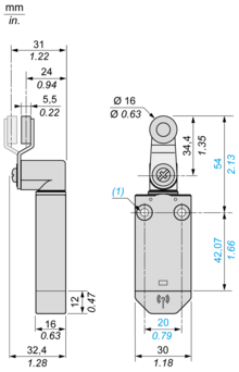
Technical Drawings
Dimensions
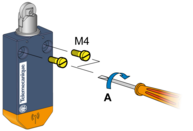
Screw Mounting
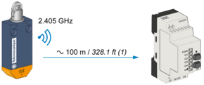
Unobstructed Mounting
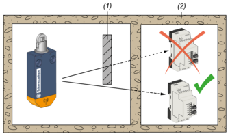
Mounting in a Metal Cabinet
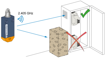
Signal Attenuation According to the Material
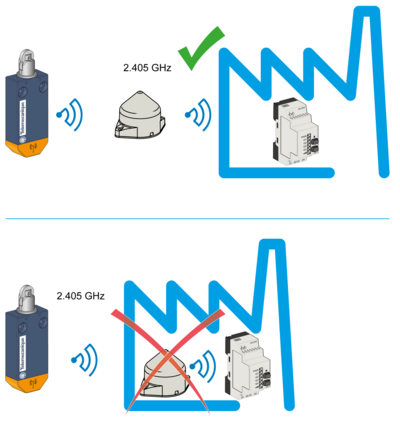
Mounting Tips for Antenna
Optimized Installation
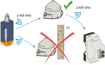
Mounting Tips for Antenna
The Relay Antenna is used to Bypass an Obstacle and/or Increase the Range
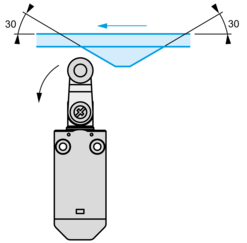
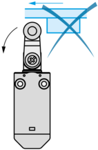
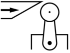
Mounting with roller lever
Recommended Mounting
Mounting with roller lever
Mounting to be Avoided
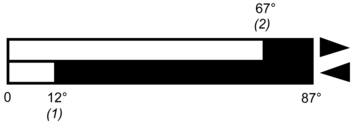
Characteristics of Actuation
Technical Description
Functional Diagram, Travel Distance
Expand all
Documents & Downloads
Document name
Date
Size
10/2/2020
117999
10/2/2020
1707318
10/2/2020
226392
10/2/2020
23863
10/2/2020
25404
10/2/2020
25847
10/2/2020
26075
10/2/2020
26427
10/2/2020
31509
10/2/2020
33679
10/2/2020
39639
10/2/2020
41386
10/2/2020
41990
10/2/2020
42323
10/2/2020
47966
10/2/2020
57781
10/2/2020
62290
Document name
Date
Size
2024-02-07
4611944
2024-02-07
4578529
Document name
Date
Size
Document name
Date
Size
2018-11-01
2228349
Document name
Date
Size
2025-08-11
221157
2025-08-11
210790
Document name
Date
Size
2024-01-17
622787
Document name
Date
Size
2021-02-01
1446501
Expand all
Related products & accessories
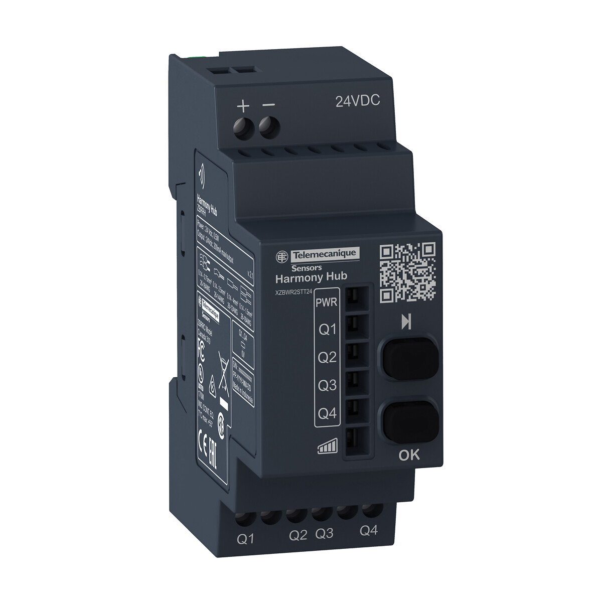
XZBWR2STT24
Programmable receiver, 4 PNP, 200 mA, 24 V DC, 2 pusbuttons, 6 LEDs
Back to top