XCSRC32M12
Preventa RFID safety switch, Telemecanique Safety switches XCS, contactless Daisy Chain model, 2 new re pairing enabled

Commercialised
Expand all
Datasheet
Range of product
Telemecanique Safety switches XCS
Product or component type
Preventa RFID safety switch
Component name
XCSRC
Design
Rectangular, standard
Size
Transponder: 50 x 15 x 15 mm, reader: 119.6 x 30 x 15 mm
Material
Valox
Electrical connection
2 male connectors
Connector type
M12 male
Type of output stage
Solid-state, PNP
Safety outputs
2 NO
Local signalling
Green, orange and red 2 multi-colour LEDs
Approach directions
3 directions-transponder with rotary sensing face
[Ue] rated operational voltage
24 V DC (- 20...10 %)SELV or PELV conforming to IEC 60204-1
Protection type
Short-circuit protection
Switching capacity in mA
200 mA
Switching frequency
<= 0.5 Hz
Discordance time
120 ms + 18 ms per additional switch connected in series
Response time
120 ms + 50 ms typical per additional switch connected in series
Delay first up
5 SECOND
Tightening torque
< 1.5 N.m
Standards
IEC 60947-5-2
IEC 60947-5-3
ISO 14119
IEC 60947-5-3
ISO 14119
Product certifications
CSA 22-2
E2
Ecolab
FCC
IC
RCM
TÜV
E2
Ecolab
FCC
IC
RCM
TÜV
Marking
CE
cULus
EAC
FCC
IC
RCM
TÜV
cULus
EAC
FCC
IC
RCM
TÜV
Safety level
SIL 3 conforming to IEC 61508, SILCL 3 conforming to IEC 62061, PL = e conforming to ISO 13849-1, category 4 conforming to ISO 13849-1
Safety reliability data
PFHD = 5E-10/h conforming to IEC 62061, PFHD = 5E-10/h conforming to ISO 13849-1
Vibration resistance
10 gn (f= 10-150 Hz) conforming to IEC 60068-2-6
Shock resistance
30 gn for 11 ms conforming to IEC 60068-2-27
Electrical shock protection class
Class III conforming to IEC 61140
IP degree of protection
IP65 conforming to IEC 60529, IP66 conforming to IEC 60529, IP67 conforming to IEC 60529, IP69K conforming to DIN 40050
Unit type of package 1
PCE
Number of units in package 1
1
Package 1 height
3.3 CENTIMETER
Package 1 width
14.8 CENTIMETER
Package 1 length
17.5 CENTIMETER
Package 1 weight
0.106 KILOGRAM
Unit type of package 2
S01
Number of units in package 2
12
Package 2 height
15 CENTIMETER
Package 2 width
15 CENTIMETER
Package 2 length
40 CENTIMETER
Package 2 weight
1.447 KILOGRAM
Indivisible sale quantity
1
California proposition 65
WARNING: This product can expose you to chemicals including: Diisononyl phthalate (DINP), which is known to the State of California to cause cancer, and Di-isodecyl phthalate (DIDP), which is known to the State of California to cause birth defects or other reproductive harm. For more information go to www.P65Warnings.ca.gov
Expand all
Technical Drawings
Dimensions
Connections
M12 Connectors, 5-pin
- (1) + 24 VDC
- (2) OSSD2 (O2)
- (3) 0 VDC
- (4) OSSD1 (O1)
- (5) Diagnosis Out (Do)
M12 Connectors, 5-pin
- (1) + 24 VDC
- (2) OSSD2 (O2)
- (3) 0 VDC
- (4) OSSD1 (O1)
- (5) Diagnosis Out (Do)
- (1) + 24 VDC
- (2) INPUT 2 (I2)
- (3) 0 VDC
- (4) INPUT 1 (I1)
- (5) Diagnosis In (Di)
Connections
Wiring Diagram: Series Connection
- (1) Start
- (2) Power circuit
- (3) Loopback device
- (4) M12/M12 female jumpers
- (5) Pre-wired female connectors
- (6) Diagnostic module (option)
Mounting and Clearance
Mounting and Clearance
Face to Face Mounting (Preferred Configuration)
- e min. > 2 mm. (e: recommended minimum mounting distance between transponder and reader)
- d : Detection limit
Mounting and Clearance
Side by Side Mounting
- e: Recommended minimum mounting distance between transponder and reader.
Mounting and Clearance
Minimum Mounting Clearances between Safety Switches
Detection Curves
Face to Face Mounting (Preferred Configuration)
- Sar: Assured release distance
- Sao: Assured operating distance
- (1) Recommended minimum mounting distance between transponder and reader.
Detection Curves
- Sar: Assured release distance
- Sao: Assured operating distance
- (1) Recommended minimum mounting distance between transponder and reader.
- Sar: Assured release distance
- Sao: Assured operating distance
- (1) Recommended minimum mounting distance between transponder and reader.
Detection Curves
Side by Side Mounting
- Sar: Assured release distance
- Sao: Assured operating distance
- (1) X=0 for X<0
- (2) X=0 for X>0
- (3) Recommended minimum mounting distance between transponder and reader.
Detection Curves
- Sar: Assured release distance
- Sao: Assured operating distance
- (1) X=0 for X<0
- (2) X=0 for X>0
- (3) Recommended minimum mounting distance between transponder and reader.
- Sar: Assured release distance
- Sao: Assured operating distance
- (1) X=0 for X<0
- (2) X=0 for X>0
- (3) Recommended minimum mounting distance between transponder and reader.
Expand all
Documents & Downloads
Document name
Date
Size
2024-10-31
31713778
Document name
Date
Size
2017-03-01
2329593
2024-12-02
256729340
2024-12-02
4814059
Document name
Date
Size
Document name
Date
Size
7/18/2024
144953
7/18/2024
21532
7/18/2024
22068
7/18/2024
22746
7/18/2024
22807
7/18/2024
23123
7/18/2024
24866
7/18/2024
252650
7/18/2024
2653466
7/18/2024
30707
7/18/2024
31822
7/18/2024
33080
7/18/2024
51231
7/18/2024
74342
7/18/2024
80203
Document name
Date
Size
2025-02-28
239900
2025-05-19
242165
Document name
Date
Size
2024-06-27
191465
Document name
Date
Size
Document name
Date
Size
2026-01-26
4343561
Expand all
Related products & accessories
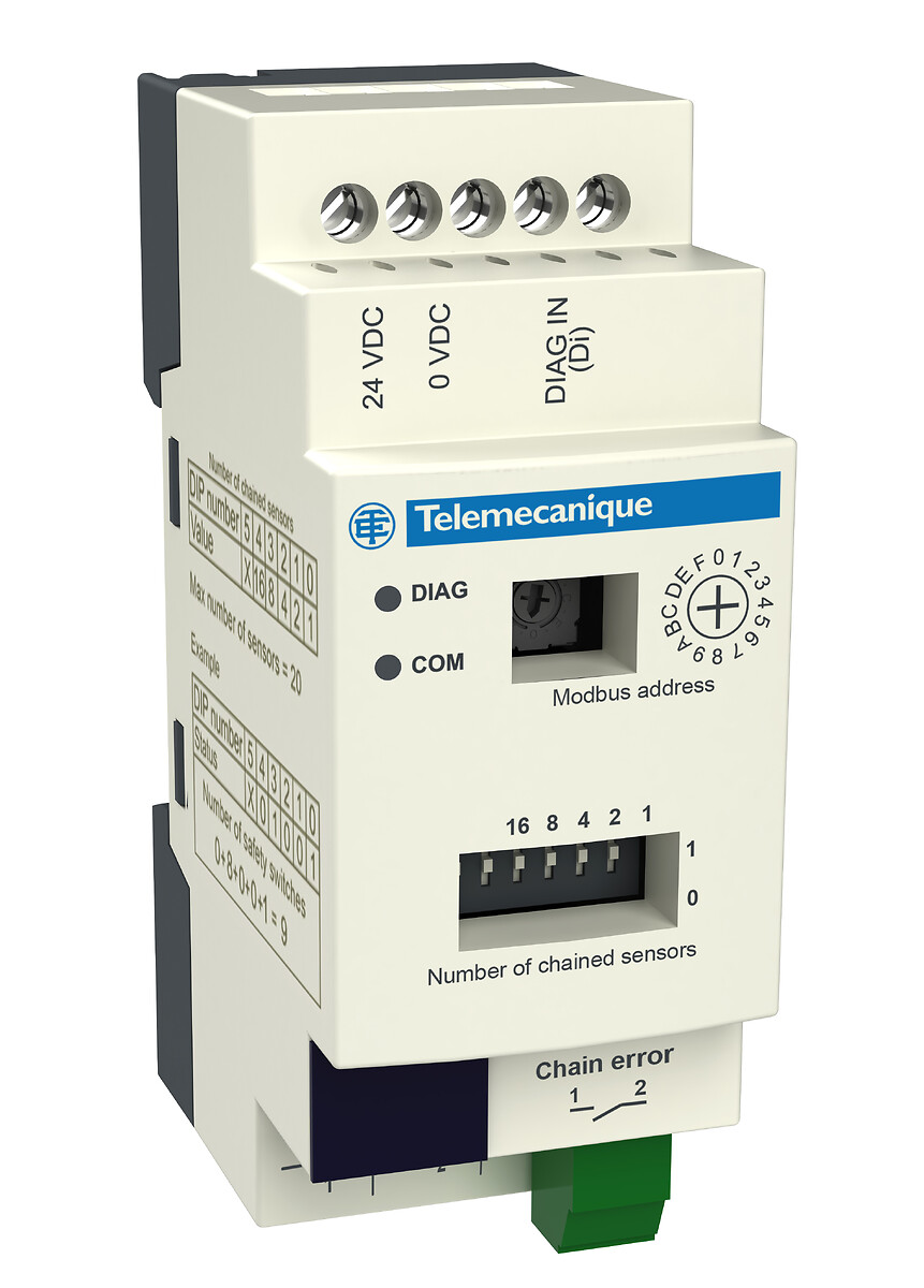
XCSRD210MDB
Telemecanique Safety switches XCS, diagnostic module for XCSRC Daisy Chain models, Modbus RTU
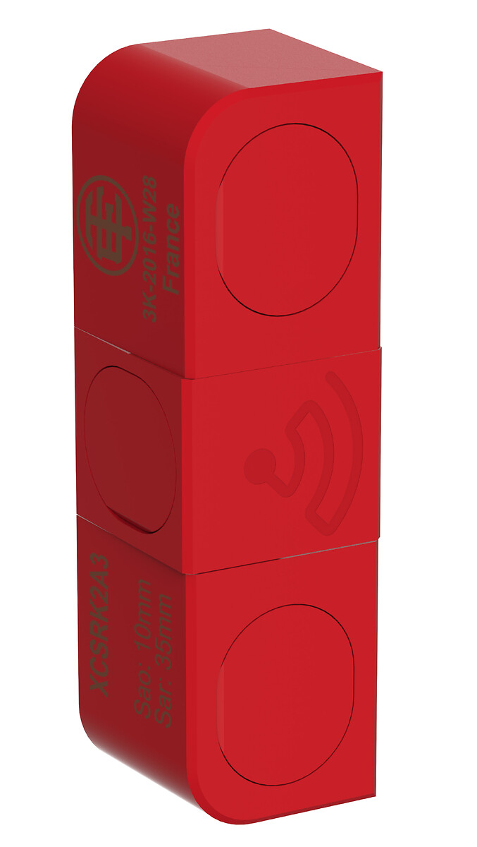
XCSRK2A3
Telemecanique Safety switches XCS, Blank RFID Transducer for XCSRC3xxx
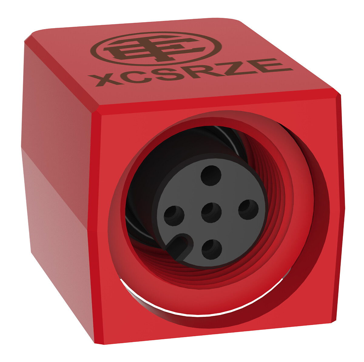
XCSRZE
M12 plug for XCSRC Daisy Chain models, Telemecanique Safety switches XCS, Loopback device
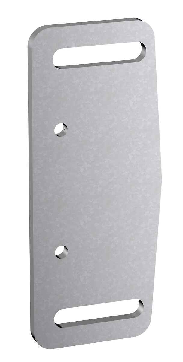
XCSRZSRC1
Telemecanique Safety switches XCS, Steel fixing plate for RFID Reader XCSRC**
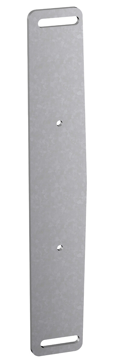
XCSRZSTK1
Telemecanique Safety switches XCS, Steel fixing plate for RFID Transducer XCSRK2A*
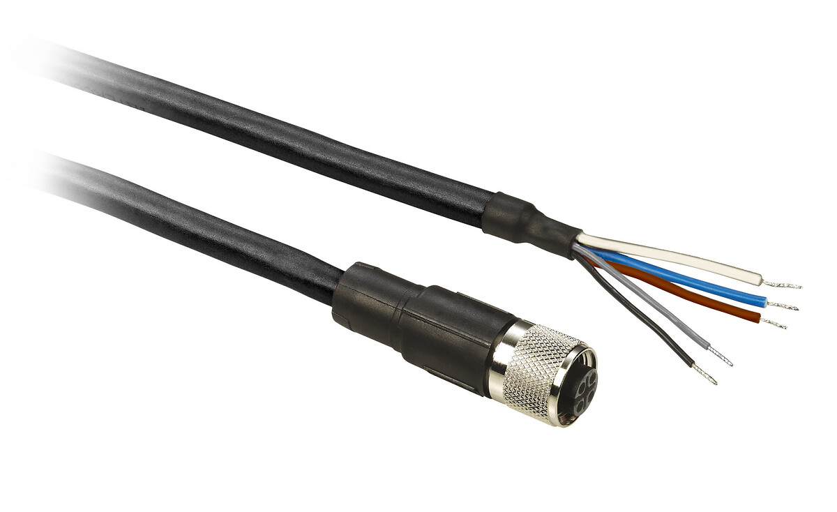
XZCP11V12L2
Pre wired connectors XZ, straight female, M12, 5 pins, cable PUR 2 m
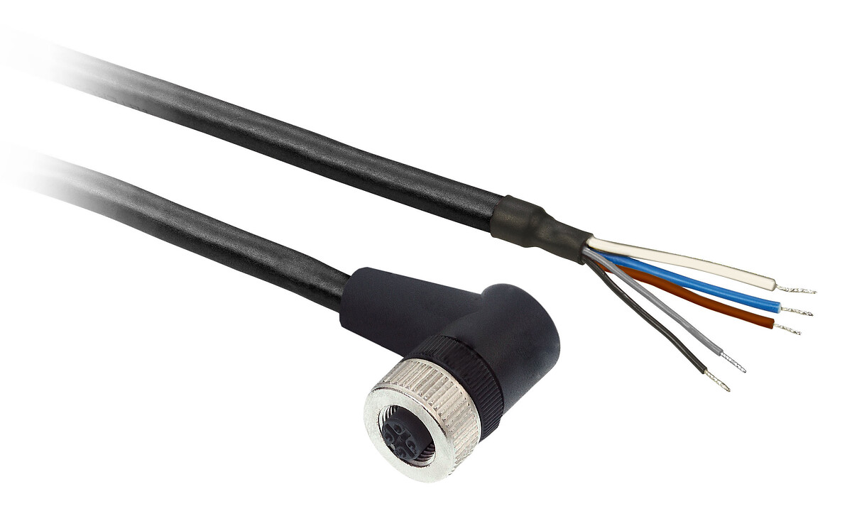
XZCP12V12L2
Pre wired connectors XZ, elbowed female, M12, 5 pins, cable PUR 2 m
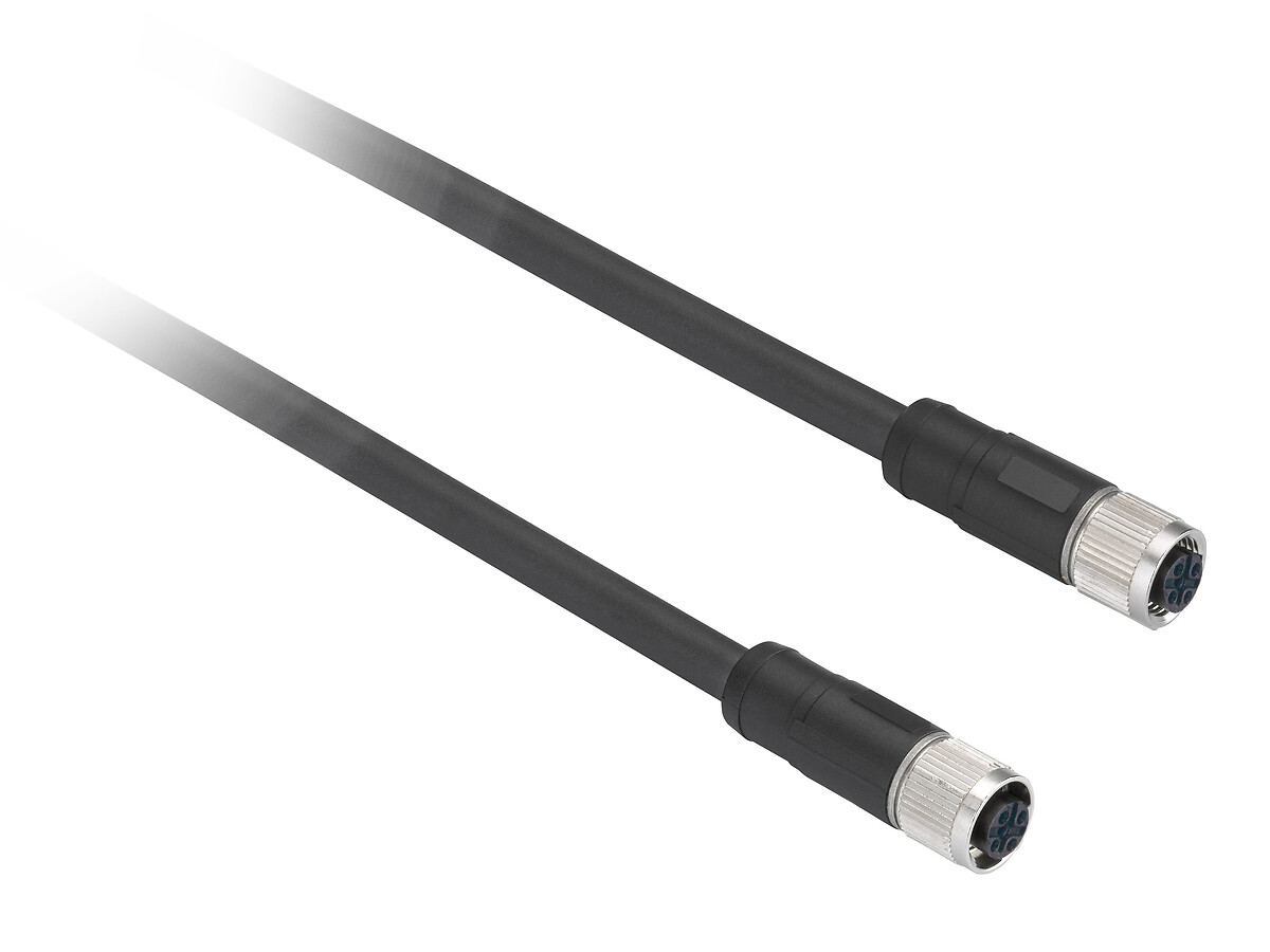
XZCR1111064D3
Telemecanique Safety light curtains XUSL, Series connection jumper, 2 straight M12, Female/Female con, 3 m, 5 pins
Back to top