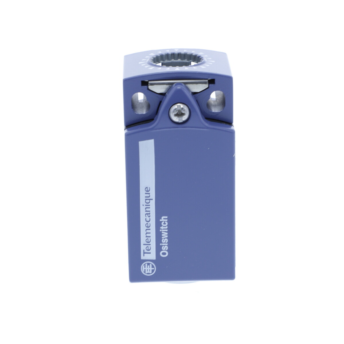
XCMD2517L1
Limit switch, Limit switches XC Standard, XCMD, steel ball bearing mount. roller lev., 1NC+1 NO, slow, 1 m

COMMERCIALISED
Expand all
Datasheet
Range of product
Telemecanique Limit switches XC Standard
Series name
Standard format
Product or component type
Limit switch
Device short name
XCMD
Sensor design
Miniature
Body type
Fixed
Head type
Rotary head
Material
Metal
Body material
Zamak
Head material
Zamak
Fixing mode
By the body
Movement of operating head
Rotary
Type of operator
Spring return roller lever metal ball bearing mounted
Type of approach
Lateral approach, 2 directions
Contacts type and composition
1 NC + 1 NO
Contact operation
Slow-break
Tracks
24/31 mm
Switch actuation
By 30° cam
Electrical connection
Removable cable connector
Cable composition
5 x 0.75 mm²
Wire insulation material
PvR
Contacts insulation form
Zb
Positive opening
With
Contact code designation
B300, AC-15 (Ue = 240 V), Ie = 1.5 A conforming to IEC 60947-5-1 appendix A, R300, DC-13 (Ue = 250 V), Ie = 0.1 A conforming to IEC 60947-5-1 appendix A
Resistance across terminals
25 mOhm conforming to IEC 60255-7 category 3
Shock resistance
25 gn for 18 ms conforming to IEC 60068-2-27
Vibration resistance
25 gn (f= 10-500 Hz) conforming to IEC 60068-2-6
IP degree of protection
IP66 conforming to IEC 60529, IP67 conforming to IEC 60529, IP68 conforming to IEC 60529
IK degree of protection
IK06 conforming to IEC 62262
Overvoltage category
Class I conforming to IEC 61140, class I conforming to NF C 20-030
Protective treatment
TC
Product certifications
CCC
CSA
UL
CSA
UL
Standards
CSA C22.2 No 14
IEC 60204-1
IEC 60947-5-1
UL 508
IEC 60204-1
IEC 60947-5-1
UL 508
Unit type of package 1
PCE
Number of units in package 1
1
Package 1 height
3.3 CENTIMETER
Package 1 width
12.5 CENTIMETER
Package 1 length
13 CENTIMETER
Package 1 weight
0.214 KILOGRAM
Unit type of package 2
S03
Number of units in package 2
50
Package 2 height
30 CENTIMETER
Package 2 width
30 CENTIMETER
Package 2 length
40 CENTIMETER
Package 2 weight
11.491 KILOGRAM
Unit type of package 3
BAG
Number of units in package 3
1
Package 3 height
3.3 CENTIMETER
Package 3 width
12.5 CENTIMETER
Package 3 length
13 CENTIMETER
Package 3 weight
0.214 KILOGRAM
Indivisible sale quantity
1
California proposition 65
WARNING: This product can expose you to chemicals including: Diisononyl phthalate (DINP), which is known to the State of California to cause cancer, and Di-isodecyl phthalate (DIDP), which is known to the State of California to cause birth defects or other reproductive harm. For more information go to www.P65Warnings.ca.gov
Expand all
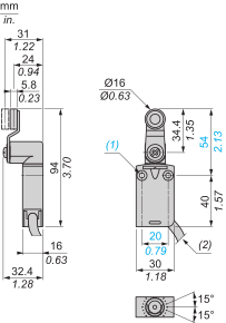
Technical Drawings
Dimensions
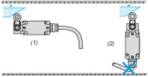
Mounting
Sweep of Connecting Cable
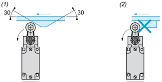
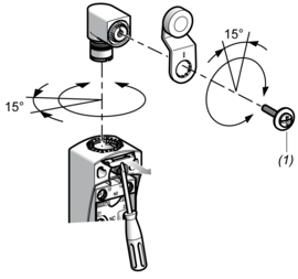
Mounting with Rotary Heads and Levers
Type of Cam
Setting-up with Head ZCE01 and ZCE09
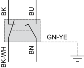
Wiring Diagram
2-pole N/C + N/O Break before Make, Slow Break
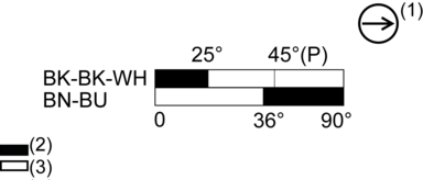
Characteristics of Actuation
Switch Actuation by 30° Cam

Functional Diagram
Expand all
Documents & Downloads
Document name
Date
Size
2024-07-15
68162797
Document name
Date
Size
7/18/2024
125952
7/18/2024
20697
7/18/2024
21048
7/18/2024
217170
7/18/2024
21781
7/18/2024
22103
7/18/2024
23563
7/18/2024
23992
7/18/2024
24118
7/18/2024
24851
7/18/2024
25687
7/18/2024
31971
7/18/2024
32389
7/18/2024
38679
7/18/2024
49804
7/18/2024
51076
Document name
Date
Size
2026-04-14
110143
2026-04-13
108872
Document name
Date
Size
2024-10-15
216088
Back to top