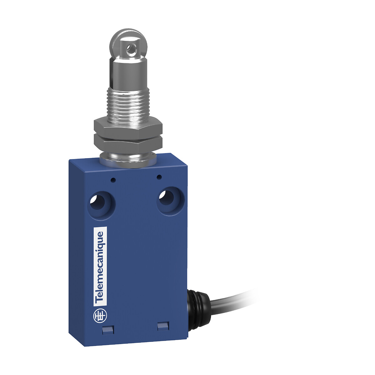
XCMH21F2L2
XCMH Limit Switches Miniature Plastic M12 head metal roller plunger NC + NO Snap L2

Commercialised
Expand all
Datasheet
Range of product
Telemecanique Limit switches XC Standard
Series name
Standard format
Product or component type
Limit switch
Device short name
XCMH
Sensor design
Miniature
Body type
Fixed
Head type
M12 plunger head
Material
Plastic
Body material
Plastic
Head material
Zamak
Fixing mode
By the head
Movement of operating head
Linear
Type of operator
Spring return roller plunger metal
Type of approach
Lateral approach, 2 directions
Contacts type and composition
1 NC + 1 NO
Contact operation
Snap action
Switch actuation
By 30° cam
Electrical connection
Fixed cable
Cable composition
4 x 0.34 mm²
Wire insulation material
PvR
Contacts insulation form
Zb
Positive opening
With
Contact code designation
C300, AC-15 (Ue = 240 V), Ie = 0.75 A conforming to IEC 60947-5-1 appendix A, R300, DC-13 (Ue = 250 V), Ie = 0.1 A conforming to IEC 60947-5-1 appendix A
Resistance across terminals
25 MOhm conforming to IEC 60255-7 category 3
Shock resistance
25 gn for 18 ms conforming to IEC 60068-2-27
Vibration resistance
5 gn (f= 10-500 Hz) conforming to IEC 60068-2-6
IP degree of protection
IP66 conforming to IEC 60529, IP67 conforming to IEC 60529
IK degree of protection
IK04 conforming to IEC 62262
Electrical shock protection class
Class II conforming to IEC 61140, class II conforming to NF C 20-030
Protective treatment
TC
Product certifications
CCC
CSA
UL
CSA
UL
Standards
CSA C22.2 No 14
IEC 60204-1
IEC 60947-5-1
UL 508
IEC 60204-1
IEC 60947-5-1
UL 508
Unit type of package 1
PCE
Number of units in package 1
1
Unit type of package 2
S03
Number of units in package 2
40
Package 2 height
30 CENTIMETER
Package 2 width
30 CENTIMETER
Package 2 length
40 CENTIMETER
Package 2 weight
5.1 KILOGRAM
Indivisible sale quantity
1
California proposition 65
WARNING: This product can expose you to chemicals including: Diisononyl phthalate (DINP), which is known to the State of California to cause cancer, and Di-isodecyl phthalate (DIDP), which is known to the State of California to cause birth defects or other reproductive harm. For more information go to www.P65Warnings.ca.gov
Expand all
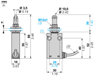
Technical Drawings
Dimensions
Dimensions
Mounting and Clearance
Mounting and Clearance
Mounting: distance required for connection

Mounting and Clearance
Sweep of Connecting Cable
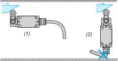
Mounting and Clearance
Mounting with Spacers
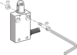
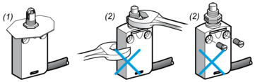
Panel Mounting
Mounting and Fixing Limit Switches by the Head
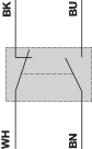
Wiring diagram
Wiring diagram
2-pole NC + NO snap action
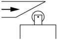
Characteristics of Actuation
Switch Actuation by 30° Cam
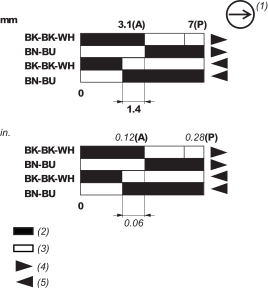
Functional Diagram
Functional Diagram
Expand all
Documents & Downloads
Document name
Date
Size
2024-07-15
68162797
Document name
Date
Size
2025-04-25
220998
2025-04-25
237213
Document name
Date
Size
2024-02-27
214476
2024-02-27
176465
Document name
Date
Size
2024-04-01
2293319
2023-08-13
2361292
Document name
Date
Size
6/1/2023
136101
6/1/2023
21858
6/1/2023
242905
6/1/2023
246446
6/1/2023
25289
6/1/2023
253039
6/1/2023
276351
6/1/2023
4444008
6/1/2023
467006
6/1/2023
49191
6/1/2023
62580
6/1/2023
78807
6/1/2023
80212
6/1/2023
82937
Expand all
Related products & accessories
XCMH21F0L1
XCMH Limit Switches Miniature Plastic M12 head metal plunger NC + NO Snap L1
XCMH21F0L2
XCMH Limit Switches Miniature Plastic M12 head metal plunger NC + NO Snap L2
XCMH21F2L1
XCMH Limit Switches Miniature Plastic M12 head metal roller plunger NC + NO Snap L1
Back to top